Key Takeaways
-
Custom power supplies are engineered to meet specific voltage, current, environmental, and form-factor requirements that off-the-shelf units often cannot cover.
- A robust design flow covers topology selection, component sizing, thermal design, PCB layout, and safety/EMC compliance (e.g., IEC/UL 62368-1, IEC 60601-1 for medical, CISPR 32/35 for EMC).
- Modern switching topologies (e.g., LLC resonant, synchronous rectification, GaN/SiC) can achieve peak efficiencies in the 90–95% range in optimized designs, depending on operating conditions and system constraints.
- Validation includes load/line regulation, ripple, transient response, thermal, reliability, and EMC testing.
- Cost optimization balances performance, compliance, manufacturability, and lifecycle/obsolescence planning.
Last updated: March 2025
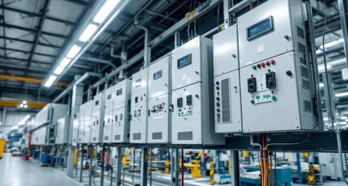
Why Custom Power Supplies?
Modern systems—from renewable energy and telecom to medical devices and battery energy storage—often require non-standard voltages, isolation, reliability levels, or mechanical envelopes. Custom design aligns the power stage to the real load profile, integration needs (e.g., BMS, PLC, CAN/PMBus), and the regulatory landscape.

What “Custom” Actually Means
Custom power supply engineering spans:
-
Electrical: topology choice, magnetics, semiconductors (Si, GaN, SiC), control algorithms.
-
Mechanical/Thermal: form factor, cooling strategy, heatsinks, airflow, vibration constraints.
-
Safety & EMC: insulation system, creepage/clearance, protective earth, emissions/immunity.
-
System Integration: interfaces (I²C/PMBus/CAN/Ethernet), telemetry, and energy management.
Core Subsystems
-
Input stage: inrush limiting, surge protection, filtering, and (if required) PFC.
-
Power stage/topology (the “heart”): determines efficiency, power density, and EMI behavior.
-
Control: analog PWM (e.g., current-mode) or digital (adaptive loops, telemetry, PFC).
-
Output stage: rectification, synchronous stages, LC filtering, sense/feedback networks.
Common Topologies (when to use what)
-
Flyback (to ~150 W): simple, isolated, multi-output capable. Great for chargers/aux rails.
-
Forward/Two-transistor forward (~100–500 W): higher efficiency and lower ripple than flyback.
-
LLC resonant (wide power range): very high efficiency with soft switching and low EMI—popular for high density and battery-related applications.
-
Half-/Full-Bridge (≥1 kW): robust at higher power; good regulation with appropriate control and magnetics.
Control, Protection & Feedback
-
Controllers: PWM (e.g., current-mode UCx family) or digital controllers for PFC, telemetry, adaptive dead-time, and multi-phase coordination.
-
Protection: Overvoltage (OVP), Overcurrent/Overload (OCP/OLP), Short-circuit (SCP), Overtemperature (OTP), input UVLO/OVLO; with coordinated fault responses.
-
Feedback stability: ensure adequate gain/phase margin and fast transient response (especially for dynamic loads/BMS).
Requirements & Specifications (get these right first)
-
Inputs: voltage windows, frequency, hold-up time, PFC requirements, surge/ESD.
-
Outputs: voltages, current ranges, ripple/noise targets, regulation, sequencing, dynamic load steps.
-
Environment: temp (often −40…+85 °C industrial), altitude, humidity, vibration/shock.
-
Safety: insulation classes, creepage/clearance, PE bonding, fault conditions.
-
Power quality & EMC: harmonics, PF, CISPR 32/35 targets, grid codes if applicable (for inverters/ESS).
-
Battery specifics (if relevant): CC/CV profiles, cell chemistry, balancing, BMS comms.
Design Process (end-to-end)
-
Requirements definition and risk analysis
-
Topology trade-off analysis (efficiency, density, cost, compliance)
-
Component selection (magnetics, capacitors, semiconductors, protection devices)
-
Simulation (electrical, thermal, EMC pre-analysis)
-
Prototype development
-
PCB layout optimization (loop areas, switch nodes, return paths, creepage/clearance)
-
Iterative testing and optimization
-
Pre-compliance testing (safety and EMC)
-
Design freeze, DFM/DFT, pilot build, certification, ramp-up
Thermal Management Considerations
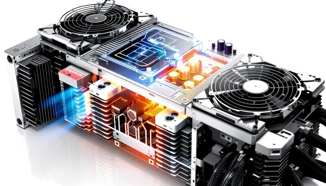
Effective thermal design addresses:
-
Conduction and switching losses
-
Core and copper losses
-
Gate-drive and auxiliary consumption
Cooling strategies may include:
-
Natural convection
-
Forced air
-
Heat pipes
-
Cold plates or liquid cooling in high-density systems
Validation should include worst-case ambient conditions, altitude derating, and capacitor hotspot analysis.
Safety and EMC Framework
Applicable standards depend on the end application and market.
Common examples:
-
IEC/UL 62368-1 (IT/AV and industrial equipment)
-
IEC 60601-1 / -1-2 (medical safety and EMC)
-
CISPR 32 / CISPR 35 (emissions and immunity)
-
EU Ecodesign (e.g., EU 2019/1782) for external power supplies
Testing typically includes:
-
Hi-pot and ground bond
-
Leakage current
-
Surge, EFT, and ESD
-
Conducted and radiated emissions
-
Conducted and radiated immunity
Requirements must always be defined during the specification phase.
Verification and Validation
Validation generally includes:
-
Load and line regulation
-
Ripple and noise
-
Efficiency across load and temperature
-
Hold-up time
-
Step-load transients
-
Startup and shutdown sequencing
-
Reliability screening (e.g., burn-in, derating review)
-
Environmental testing (thermal, humidity, vibration)
-
EMC pre-compliance before formal lab testing
Application-Specific Considerations

-
Medical: Low leakage currents, reinforced isolation, strict EMC.
-
Battery Energy Storage (BESS): Bidirectional stages, communication with BMS/EMS.
-
Industrial Automation: Noise immunity, wide temperature range, fieldbus integration.
-
Telecom: Redundancy, hot-swap capability, telemetry.
-
Renewables: Grid code compliance and harmonic limits where applicable.
Cost Optimization in Custom PSU Projects
Cost optimization involves:
-
Right-sizing specifications
-
Evaluating equivalent components with similar reliability
-
Designing for manufacturability (DFM) and testability (DFT)
-
Planning for second sources and lifecycle management
-
Balancing NRE against expected production volume
Monitoring component lifecycle status and supply chain stability remains an important consideration in long-term industrial programs.
Emerging Trends
-
Wide Bandgap Maturity (GaN & SiC):
Continued adoption in industrial and energy systems enables higher switching frequencies and improved efficiency under real-world operating conditions. -
High-Transient Loads (AI & Edge Computing):
Increasingly dynamic load profiles require faster control loops, tighter regulation, and improved power integrity design. -
Bidirectional Power Architectures:
Growth in battery energy storage and hybrid systems drives demand for bidirectional converters with high efficiency across CC–CV operation. -
Digitalization & Telemetry:
Remote diagnostics, firmware updates, and predictive maintenance are becoming standard expectations in industrial and telecom applications. -
Lifecycle & Sustainability Focus:
Obsolescence planning, component transparency, and energy efficiency compliance are gaining importance in EU markets.
Conclusion
Custom power supply design is a multidisciplinary engineering process that integrates electrical performance, safety, EMC compliance, thermal management, and lifecycle planning.
As system requirements become more application-specific, tailored designs can offer advantages in integration, efficiency, and compliance alignment. However, these benefits depend on clearly defined specifications and a structured development process.
Early definition of regulatory, environmental, and interface requirements remains critical to project success.
FAQs
What is a typical development timeline?
For a single-output custom PSU, development often ranges from approximately 12 to 20 weeks, depending on complexity and certification scope. Medical, aerospace, or energy storage applications may require additional time.
When should I choose custom over off-the-shelf?
A custom solution may be appropriate when standard products cannot meet:
-
Required output characteristics
-
Isolation levels
-
Environmental ratings
-
Mechanical constraints
-
Interface or compliance requirements
What minimum order quantities (MOQ) are typical?
MOQs commonly range from 100 to 1000 units, depending on complexity and whether non-recurring engineering (NRE) costs are amortized separately.
How does power density compare?
Optimized designs using modern topologies and wide bandgap semiconductors can achieve higher power density than general-purpose units. Typical values vary significantly by cooling method, safety spacing, and application constraints.
Which certifications are most common?
Commonly referenced standards include:
-
IEC/UL 62368-1
-
IEC 60601-1 / -1-2
-
DO-160 (aerospace, if applicable)
-
ISO 26262 (automotive functional safety)
-
CISPR 32 / CISPR 35 (EMC)
Certification requirements depend on the target application and market.


