Key takeaways
- AC-DC bidirectional power modules are commonly used as a core building block in modern battery formation and testing systems, supporting controlled charge and discharge cycles for lithium-ion cell production and validation.
- In a single hardware unit, they can operate as an AC-DC converter (charging) and as a grid-tied DC-AC inverter (regenerative discharging).
- Typical performance targets cited for this class of equipment include power factor > 0.99, THDi < 5%, and voltage accuracy around ±0.5% (values depend on model and operating point).
- Modular architectures support parallel operation for scaling from R&D setups to higher-throughput production systems, typically with automatic current sharing.
- Thermal management (often forced-air cooling) and integrated protection functions are designed to support industrial operating conditions (exact ratings depend on the product specification).
Why regenerative testing matters
Battery formation and testing are among the most energy-intensive stages in battery manufacturing. During formation, newly assembled lithium-ion cells undergo initial charge and discharge cycles that help establish stable electrochemical behavior (including development of the solid-electrolyte interphase, SEI) and screen for early defects.
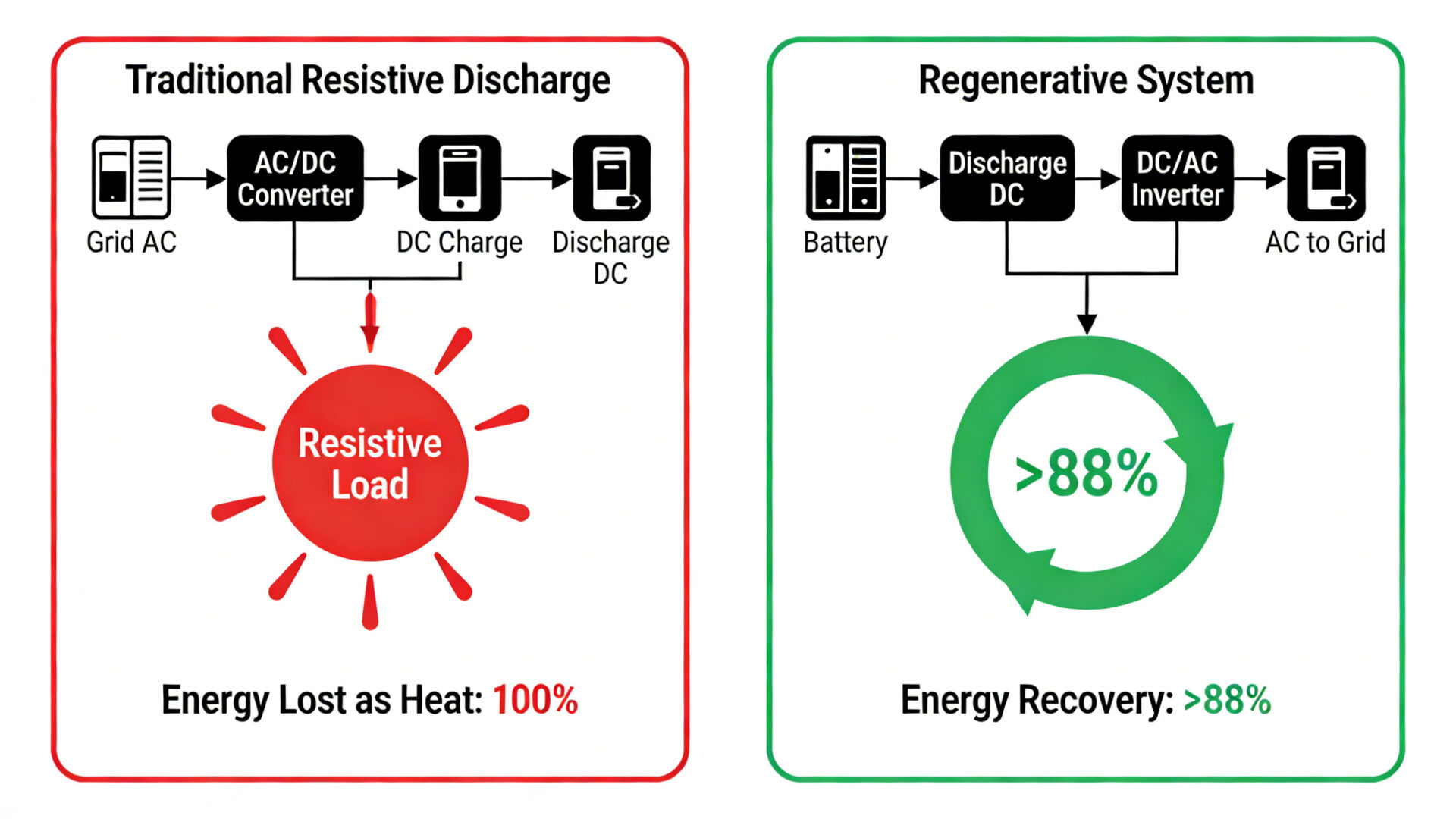
Traditional test systems often use resistive loads that dissipate discharge energy as heat. As energy costs rise and sustainability targets become more relevant, many manufacturers evaluate regenerative approaches that can feed discharge energy back into the facility’s electrical system rather than converting it into waste heat.
Core principle: unified bidirectional power conversion
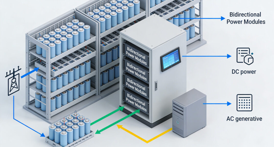
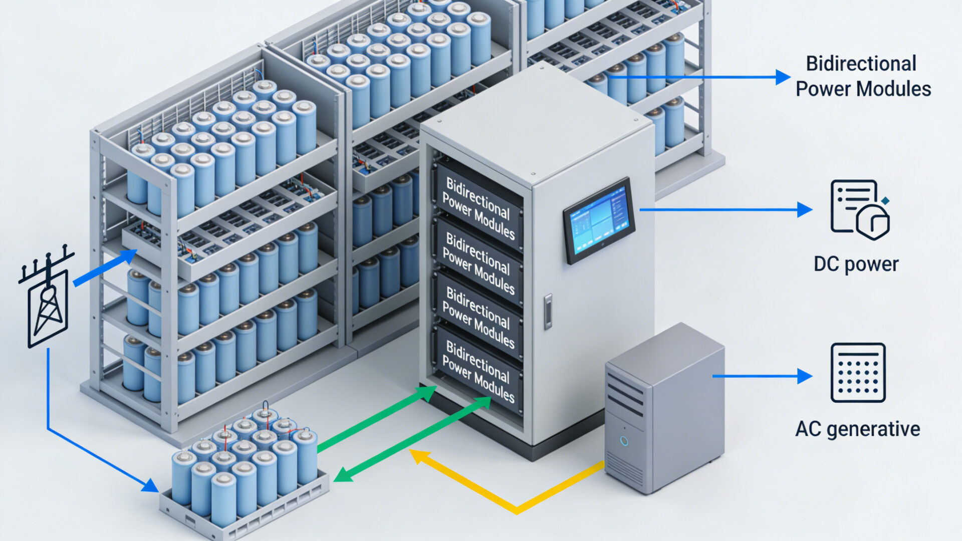
A bidirectional AC-DC power module combines charging and discharging functions within one converter:
- Charge mode (AC-DC): converts facility AC input into precisely regulated DC output for controlled charging.
- Discharge mode (DC-AC): converts battery DC energy into AC power and can return that energy to the facility’s electrical system (grid-tied operation), subject to system design and site requirements.
Compared with architectures using a dedicated AC-DC power supply plus a resistive/electronic load, this unified approach can reduce net energy draw and lower thermal dissipation at the rack level—depending on operating profile and recovery efficiency.
Technical foundation for battery applications
Power semiconductors, topology, and control
The TBM14V series is presented as an example of bidirectional module engineering for battery testing. Such systems typically use established power-conversion topologies with devices such as IGBTs or SiC MOSFETs arranged for bidirectional power flow.
In industrial environments, galvanic isolation between the AC grid and DC battery circuits is often required and is typically implemented via high-frequency transformers, particularly in multi-channel test racks.
Control architectures frequently use DSPs or FPGAs to execute charge/discharge sequences and multi-stage formation profiles with fine time resolution (implementation varies by platform).
Accuracy and stability for consistent testing
Battery formation and validation depend on repeatable electrical profiles. For bidirectional modules, commonly cited targets include:
- Voltage regulation accuracy: around ±0.5% (model-dependent)
- Low ripple: e.g., ≤ 500 mV ripple limit (as specified), to help avoid unnecessary electrochemical stress during testing
- Grid power quality in inverter mode: e.g., THDi < 5% and power factor > 0.99, supporting clean reinjection of energy into the facility supply (subject to compliance and site conditions)
Fast mode switching and scalable parallel operation
For dynamic test profiles, the ability to switch between charge and discharge modes quickly is important. The article references mode switching of < 10 ms between rectifier and inverter operation (where supported). This can enable:
- load-step response tests
- pulse testing for power capability characterization
- complex duty-cycle profiles that reflect application usage patterns
For system builders, parallel operation can enable stepwise scaling. The text references up to eight modules with automatic current sharing and imbalance below 5% (as specified). In practice, achievable sharing depends on module control strategy and installation conditions.
Core application: battery formation
What formation requires electrically
Formation typically starts with a low-current charge to support SEI development, followed by defined cycles that may include:
- rest periods
- varying C-rates
- defined depth-of-discharge (DoD) patterns
From a power-conversion standpoint, this emphasizes accurate regulation, low ripple, and repeatable profiles across channels.
Traditional limitations vs regenerative approach
With separate chargers and resistive discharge loads, discharge energy is converted to heat. This can increase:
- net energy consumption
- cooling demand and HVAC infrastructure requirements
- thermal gradients that may affect test consistency
Regenerative systems based on bidirectional modules can return a significant portion of discharge energy to the facility, reducing heat generated in the test rack. The text cites recovery efficiencies of 86% to 88.5% for DC-AC operation (as specified).
Economic impact
The article includes an example calculation: a formation line with 100 channels × 2.4 kW (240 kW total). It estimates annual energy consumption for a 24/7 resistive approach and contrasts this with a regenerative scenario using 88% discharge efficiency.
Because electricity tariffs, operating profiles, downtime, and facility power constraints vary widely, these figures should be treated as illustrative rather than predictive. For decision-making, it is typically necessary to model:
- the real duty cycle (charge/discharge ratios, rest times)
- measured facility energy costs and demand charges
- cooling energy overhead (HVAC)
- achievable recovery efficiency in the integrated system
Avoid framing payback or savings as guaranteed outcomes; they are project-specific.
Beyond formation: testing and validation use cases
After formation, typical test categories include:
- capacity verification
- cycle-life testing
- rate capability testing
- abuse / safety-oriented tests (as defined by the manufacturer’s test plan)
Bidirectional modules can be advantageous when a test program involves large energy throughput (e.g., long cycle-life tests), because regenerative operation can reduce net energy draw and heat. The article also mentions high dynamic response for pulse testing (e.g., slew rates > 1 A/µs, as specified) and built-in protections (overcurrent, overvoltage, overtemperature, reverse polarity), which can help protect equipment during fault conditions.
Energy-recovering aging tests: thermal and throughput considerations
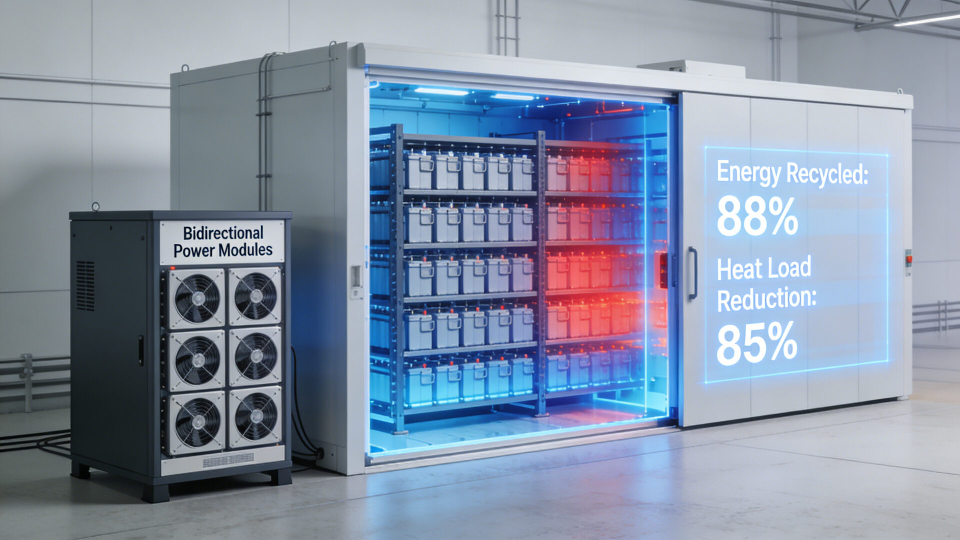
Aging tests can run for weeks or months. In resistive systems, heat generation can limit cell density in chambers and increase cooling infrastructure needs.
The article provides an example: a 50 kW rack producing ~42.5 kW waste heat with resistive discharge, versus ~6 kW thermal output at 88% regenerative efficiency. These figures illustrate how recovery efficiency can materially reduce thermal load, but actual results depend on system losses, airflow, ambient conditions, and chamber design.
Potential outcomes (site-dependent) include:
- higher pack density in chambers
- improved temperature uniformity
- reduced cooling demand and maintenance load
System integration and communications
Modern test systems combine power conversion, synchronized measurement, control, safety interlocks, and data acquisition. The article describes parallel operation coordinated by a system controller, which can support:
- complex sequence management
- safety orchestration
- high-volume logging and traceability
For connectivity, protocols such as CAN bus (real-time control/status) may be complemented by Ethernet or RS-485 (integration and logging), enabling interfaces to factory networks and MES systems where required.
Performance specifications and how they map to use
The article references the following as key specification drivers:
- AC-DC efficiency: up to 93.5% (as specified)
- DC-AC (regenerative) efficiency: 86% to 88.5% (as specified)
- Power factor: > 0.99; THDi: < 5%
- Voltage accuracy: ±0.5%; ripple: up to 500 mV (as specified)
- Environmental ratings including operation up to 45 °C (as specified)
Where the text references “no derating at 45 °C,” this should be interpreted strictly as a rated condition per the manufacturer specification, not a blanket guarantee for every installation.
The text also references voltage and current ranges (e.g., ~14 V DC output and currents in the ~161 A to 189 A range). Applicability depends on the actual cell configuration and rack architecture.
Compliance and certifications (scope carefully)
The text lists certifications such as UL, CE, TÜV, and RoHS. In published form, it is safer and more accurate to state:
- certifications/markings may be available depending on product variant, configuration, and target market
- conformity should be verified against the specific model documentation and the intended installation context
This avoids implying universal certification coverage.
Outlook: next-generation battery technologies
As cell chemistries evolve (e.g., silicon-anode concepts, solid-state electrolytes, lithium-metal approaches), formation and test profiles may require different voltage plateaus, dynamics, and environmental constraints. Bidirectional modules with fast control loops and appropriate semiconductor technology may provide flexibility for advanced test strategies, particularly when combined with more adaptive control and data analysis.
Future integration into broader energy management concepts (e.g., facility microgrids, demand response) is possible in principle, but feasibility depends on local grid codes, site infrastructure, and system design.
Conclusion
AC-DC bidirectional power modules are a key enabling technology for regenerative battery formation and testing architectures. By combining controlled charging with grid-tied regenerative discharge in a modular form factor, they can reduce net energy consumption and rack-level heat generation while supporting scalable system designs.
For manufacturers and system integrators, the benefits should be evaluated with site-specific operating profiles, energy tariffs, grid constraints, and verified product specifications—especially when projecting economic outcomes.
: 14V Power Platform for Cell Formation, Energy-Recycling Aging, and Grid-Connected Test Systems")

