
As electronic systems continue to increase in speed, density, and functional integration, accurately measuring high-frequency signals has become a fundamental requirement in development, validation, and diagnostics. From high-speed communication interfaces to fast switching power supplies, signal integrity directly affects system reliability, electromagnetic compatibility, and overall performance.
Modern digital oscilloscopes with sufficient bandwidth, deep memory, and advanced analysis functions—such as those offered by Micsig—provide engineers with the technical means to observe and analyze these signals. However, reliable high-frequency measurement depends not only on the instrument itself, but equally on correct configuration, appropriate probing, and a structured measurement workflow.
This guide presents a practical and methodical framework for high-frequency oscilloscope measurements. It explains essential specifications, instrument and probe selection, step-by-step setup procedures, and systematic troubleshooting techniques commonly used in real-world signal integrity analysis.
Discover TPS digital oscilloscopes designed for signal analysis, development, validation, and diagnostic tasks in industrial and laboratory environments. The portfolio covers benchtop, tablet-based, and portable instruments, supporting applications from high-resolution measurements to field diagnostics and automated test setups.

MHO3-3504
High-resolution digital oscilloscope with 12-bit vertical resolution, suitable for detailed signal integrity and power analysis.
View product
MHO3-5004
High-bandwidth, high-resolution oscilloscope for advanced signal analysis in development and validation environments.
View product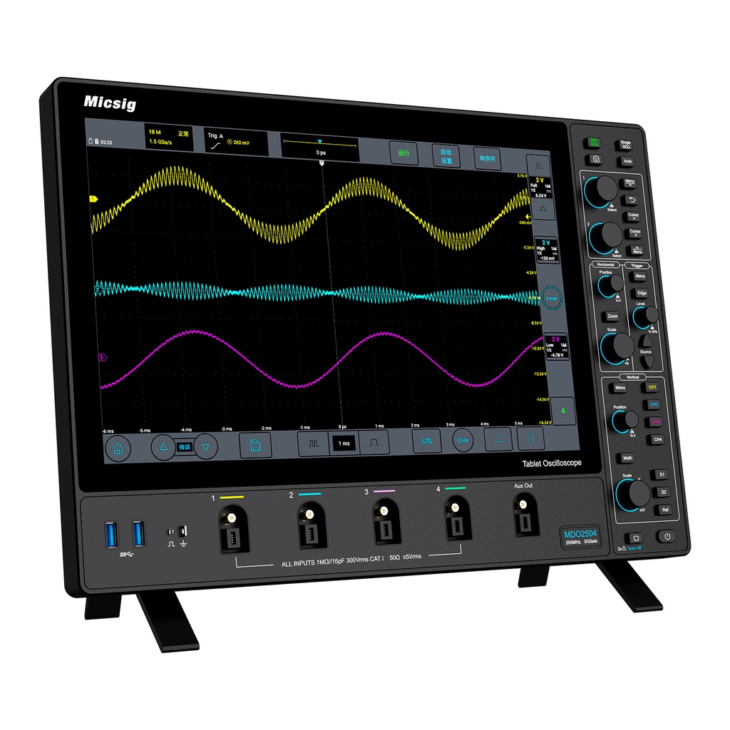
MDO5004
Benchtop digital oscilloscope designed for long acquisition windows, protocol analysis, and multi-channel measurements.
View product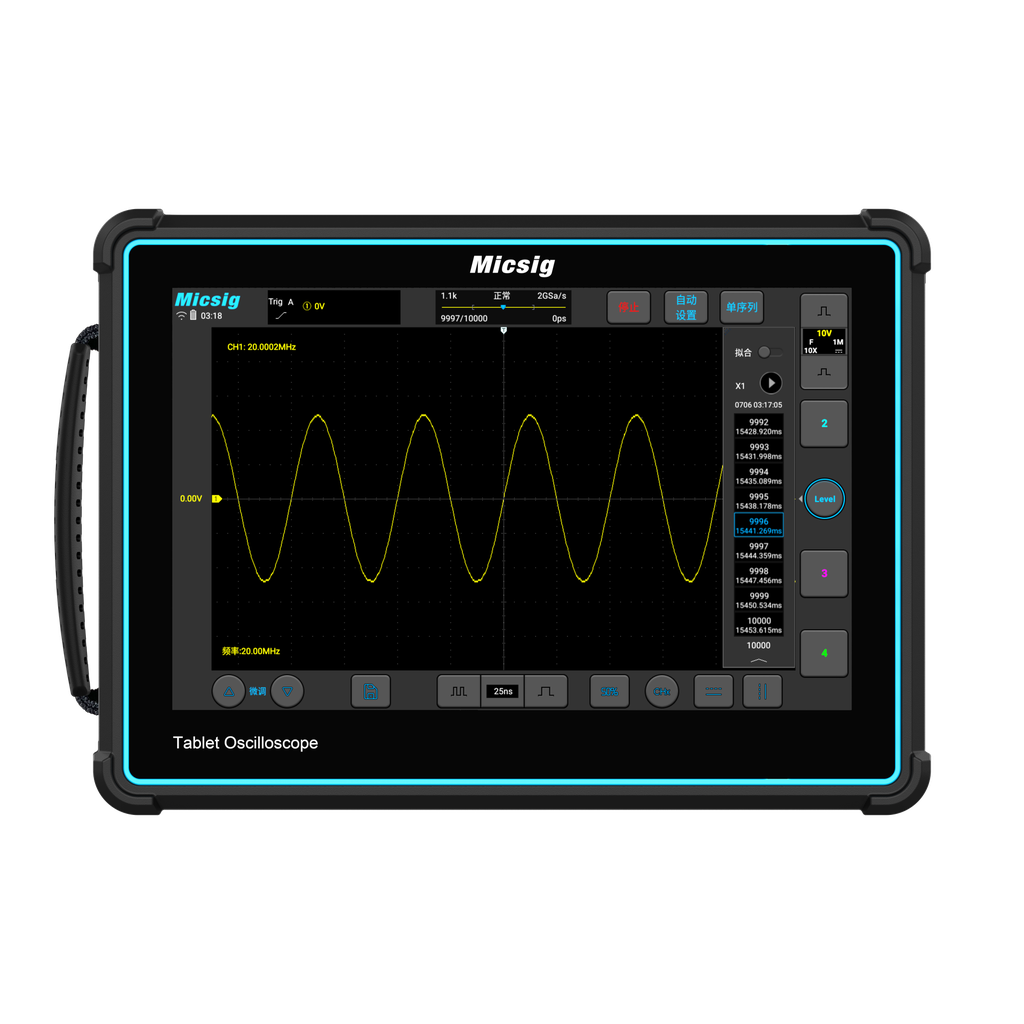
TO2002
Compact portable oscilloscope for mobile measurements, commissioning, and on-site diagnostics.
View product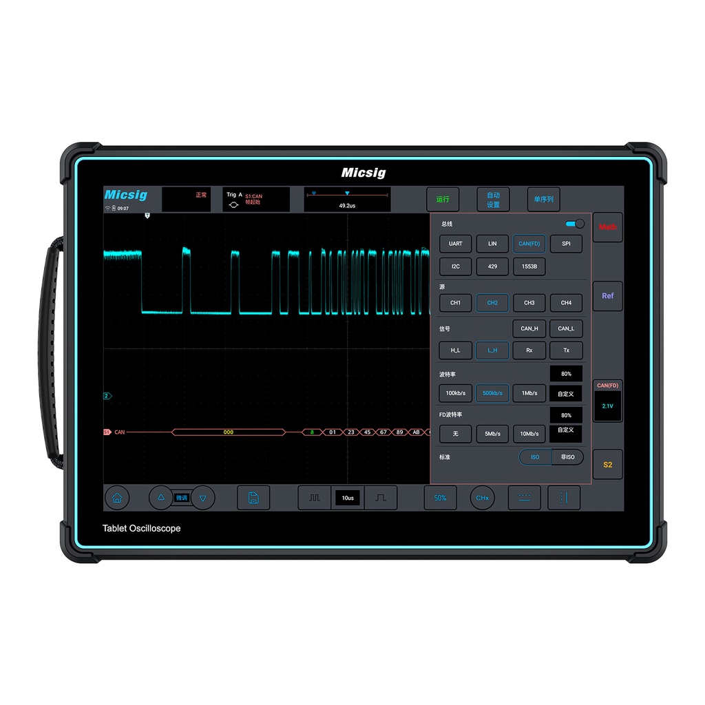
ETO3504
Tablet-based digital oscilloscope combining deep memory and touchscreen operation for flexible lab and field use.
View product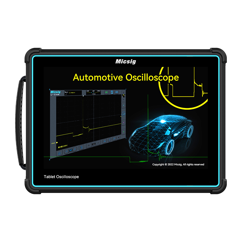
ATO1004
Automotive-focused oscilloscope with predefined test functions for vehicle electronics diagnostics.
View product
VATO2004
Split-type automotive oscilloscope for flexible measurements in confined or mobile diagnostic environments.
View productKey Takeaways
- For accurate high-frequency measurements, oscilloscope bandwidth should typically be three to five times higher than the highest relevant frequency component of the signal.
- Deep memory enables high sampling rates over extended time windows, which is essential when analyzing long data sequences or intermittent events.
- Probe selection—whether passive, differential, or current probes—directly influences measurement accuracy, signal loading, and noise susceptibility.
- Integrated features such as serial bus decoding, segmented memory, and remote operation support efficient system-level debugging and analysis.
- A disciplined setup and troubleshooting workflow helps isolate noise, distortion, and sporadic faults more efficiently.

I. Understanding the Modern Oscilloscope in High-Frequency Applications
An oscilloscope is fundamentally a measurement instrument that visualizes voltage as a function of time. Modern digital storage oscilloscopes extend this role by capturing transient events, performing automated measurements, and enabling both time-domain and frequency-domain analysis.
In high-frequency applications, accurate signal acquisition and timing resolution are critical. Signals with fast rise times or RF content contain significant high-frequency components that must be preserved by the measurement system. If bandwidth or sampling performance is insufficient, displayed waveforms may appear misleading, potentially resulting in incorrect conclusions during debugging or validation.
For this reason, contemporary oscilloscopes are designed with high-speed analog front ends, fast ADCs, and deep acquisition memory, allowing engineers to observe signal behavior with greater confidence.
Core Specifications: Bandwidth, Sample Rate, and Memory
Three specifications largely define an oscilloscope’s suitability for high-frequency measurement tasks:
Bandwidth
Bandwidth specifies the frequency at which signal amplitude is attenuated by –3 dB. For fast digital or RF signals, bandwidth must extend well beyond the fundamental frequency to preserve edge shape, rise time, and amplitude accuracy.
Sample Rate
Sampling rate determines how frequently the signal is digitized. If the sampling rate is too low, aliasing may occur, causing high-frequency components to appear as incorrect low-frequency artifacts.
Memory Depth
Memory depth defines how many samples can be stored per acquisition. Deep memory allows long time captures without reducing sampling rate, which is particularly important for protocol analysis, burst signals, and intermittent fault investigation.
II. Selecting the Appropriate Oscilloscope and Probes
The most suitable oscilloscope depends on signal characteristics, measurement environment, and workflow requirements. Bench-top instruments are typically used in development and validation, while portable or battery-powered models are advantageous for field diagnostics, commissioning, and service applications.
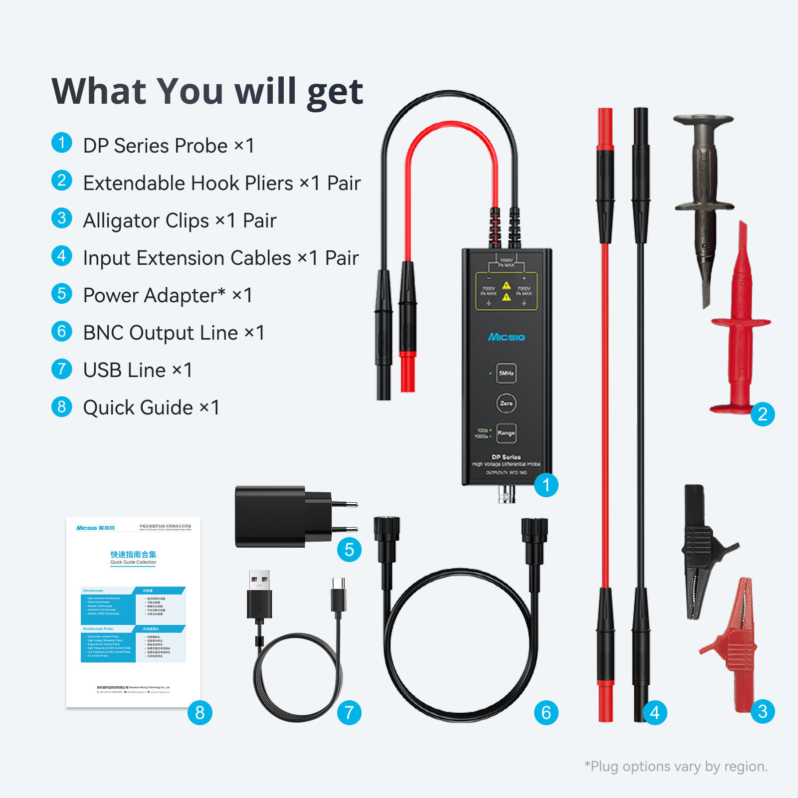
Probe Selection and Measurement Integrity
The probe forms the electrical interface between the circuit under test and the oscilloscope. Incorrect probe selection or poor grounding can significantly distort high-frequency measurements.
- Passive probes are suitable for general-purpose voltage measurements when bandwidth and loading are acceptable.
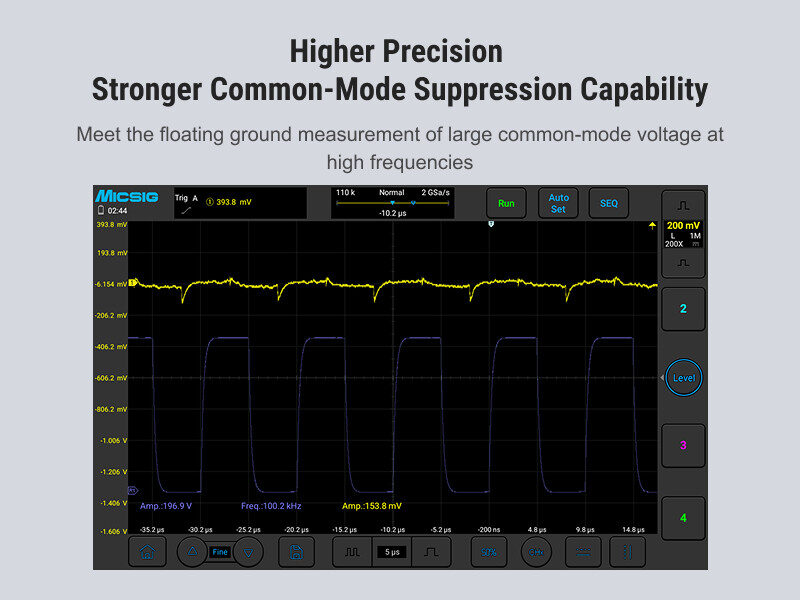
- High-voltage differential probes are required for floating or non-ground-referenced measurements, particularly in power electronics.
- Current probes enable non-intrusive current measurement across a wide frequency range.
- Optically isolated probes are used in environments with high common-mode voltage or strong electromagnetic interference.
Correct probe compensation and minimal ground lead length remain essential for reliable high-frequency signal capture.
III. Step-by-Step High-Frequency Measurement Setup
A consistent setup procedure improves repeatability and measurement confidence, especially when working with fast or low-amplitude signals.
Preparation
- Estimate signal amplitude, frequency content, and reference potential.
- Select a probe with adequate bandwidth and voltage rating.
- Perform probe compensation on each channel.
- Use the shortest possible ground connection.
Initial Configuration
- Set channel attenuation correctly.
- Adjust vertical and horizontal scales so the signal occupies most of the display.
- Configure triggering to achieve a stable waveform.
Acquisition Optimization
- Verify that the sampling rate remains sufficient at the selected time base.
- Enable deep memory when capturing long or complex signals.
- Use zoom and single-shot acquisition to inspect fine details.
- Apply bandwidth limiting only when measuring low-frequency signals in noisy environments.
IV. Advanced Analysis Techniques
High-Resolution Acquisition
Higher vertical resolution improves visibility of low-amplitude details such as power-rail ripple or small overshoot on fast edges.
Frequency-Domain Analysis
FFT functions help identify harmonic content and noise sources. Combining FFT with filtering can improve spectral clarity when analyzing interference or switching noise.
Serial Bus Decoding
Built-in decoding for protocols such as I²C, SPI, UART, CAN, and LIN simplifies digital debugging by correlating analog waveforms with decoded data.
Segmented Memory
Segmented acquisition stores only relevant triggered events, making it easier to analyze rare or intermittent faults without wasting memory on idle periods.
Remote Operation
Network connectivity and SCPI control support automated testing, long-term monitoring, and integration into validation or production workflows.
V. Systematic Troubleshooting Approach
When measurement results appear incorrect, it is advisable to begin with basic checks before assuming circuit-level faults:
- Verify probe connections and attenuation settings.
- Confirm trigger configuration and signal presence.
- Check grounding quality and environmental noise sources.
- Validate bandwidth and sampling adequacy.
- Use advanced triggers and segmented memory to capture intermittent events.
A structured diagnostic approach reduces misinterpretation and unnecessary iteration.
VI. Conclusion
Accurate high-frequency measurement relies on a balanced combination of suitable instrumentation, correct probing, and disciplined setup procedures. Modern oscilloscopes integrate high bandwidth, deep memory, and advanced analysis features that support efficient debugging across development, validation, and field applications.
While oscilloscope technology continues to evolve, the fundamental principles outlined in this guide—adequate bandwidth, appropriate probe selection, and methodical measurement practices—remain essential. Applied consistently, these principles enable engineers to gain reliable insight into signal behavior and make informed design or diagnostic decisions.


 for Accurate Measurements")