Key Takeaways
- Inrush current—also called start up current or in rush current—can reach peaks 10 to 100 times the steady‑state value, threatening circuit breakers, fuses, and power semiconductors.
- Traditional NTC thermistor based inrush current limiters are simple but suffer from cool‑down delays and continuous power loss; advanced designs integrate a bypass relay to overcome these limitations.
- DIN TS35 Mount Limiter modules offer a compact, standardized way to add peak current protection to industrial control panels, HVAC systems, lighting circuits, and UPS installations.
- Modern current limiting devices combine overcurrent protection with EMC compliance, ensuring both safety and electromagnetic compatibility in sensitive environments.
- Selecting the right current limiting module requires understanding your load type (capacitive, inductive), required steady‑state current, and environmental conditions; wide range inrush limiter models accommodate global voltage variations.
When a large motor starts, a bank of capacitors charges, or a switch‑mode power supply turns on, the initial rush of electricity—called inrush current—can be violent enough to trip breakers, weld relay contacts, or silently degrade components. For engineers and facility managers, mastering inrush current limiting is essential to ensure system reliability. This comprehensive guide covers everything from the basic physics of inrush surge current to advanced DIN rail mounted current limiting modules, helping you choose the right inrush current limiter for your application.
1. Understanding Inrush Current: The Hidden Threat
Before diving into protection methods, it is essential to answer the fundamental question: what is inrush current? Also referred to as in rush current, start up current, or current inrush, it is the instantaneous high current drawn by an electrical device when first energized. This phenomenon occurs because many loads present a very low impedance at startup. For example, discharged capacitors act as short circuits, transformer cores may saturate, and motor windings have negligible back EMF until rotation begins. The result is a massive inrush surge current that can last from microseconds to several hundred milliseconds.
In technical terms, what is an inrush current? It is the peak current that flows when power is applied, often exceeding the steady‑state current by a factor of 10 to 100. For a switch‑mode power supply with a capacitive input filter, the inrush current is limited only by the equivalent series resistance (ESR) of the capacitor and the wiring impedance. Without an inrush current limiter, these peaks can easily damage rectifiers, fuses, and circuit breakers.
1.1 Physics Behind the Surge
The magnitude of inrush surge current depends on the point on the AC waveform at which the switch closes, the residual magnetism in inductive cores, and the total circuit impedance. For a transformer, worst‑case inrush can exceed 30 times the rated current. For capacitive loads, the current surge is determined by the rate of voltage change (I = C dV/dt). Understanding these principles helps engineers design effective circuit current limiter solutions.
2. The Consequences of Uncontrolled Inrush
Unchecked inrush current can cause a cascade of problems. Circuit breakers may nuisance‑trip, fuses can blow, and relay contacts may weld shut. Even if the device survives, repeated stress on capacitors and rectifiers shortens their lifespan. In industrial settings, unexpected downtime due to tripped overcurrent protection devices can be costly. Therefore, robust peak current protection is not optional—it is a critical design requirement.
Moreover, inrush current contributes to voltage sags on the distribution network, affecting other equipment. This is why many standards now require inrush current limiting for certain product categories. A proper inrush current suppressor ensures compliance and enhances overall system stability.
3. Technologies for Inrush Current Limiting
Several technologies exist to mitigate inrush surge current, each with its own advantages and trade‑offs. The choice depends on power level, frequency of switching, ambient temperature, and cost constraints.
3.1 NTC Thermistor Based Inrush Current Limiters
The most common component for limiting inrush current is the NTC thermistor (Negative Temperature Coefficient thermistor). When cold, its resistance is high, limiting the start up current. As current flows, the thermistor self‑heats, its resistance drops to a very low value, allowing normal operation with minimal power loss. This simple mechanism provides automatic, resettable protection—hence the term soft start device is often used interchangeably with NTC‑based limiters.
However, NTC thermistors are not without limitations. They require a cool‑down period (typically seconds to minutes) before they can limit another surge; otherwise, they may not provide adequate protection for rapid power cycling. Additionally, they continuously dissipate power during normal operation, which can be a concern in energy‑sensitive or thermally constrained designs. In such cases, a more advanced inrush current limiter circuit using active bypass (e.g., a relay or triac) after startup can combine the benefits of a thermistor with fast restart capability.
3.2 Advanced Solution: Integrated Bypass Relay
To address the limitations of standalone NTC thermistors, engineers have developed inrush current limiters with an integrated bypass relay. This design is often described as “no simple NTC solution” because it adds intelligence to the limiting process. Here’s how it works:
- At power‑on, the current flows through the limiting element (typically an NTC thermistor or a power resistor), which suppresses the inrush surge current.
- After a predetermined time—usually 100‑500 ms, sufficient for bulk capacitors to charge or transformer inrush to decay—a control circuit energizes a relay.
- The relay contacts close, bypassing the limiting element entirely. During normal operation, current flows through the low‑resistance relay path, resulting in near‑zero power dissipation.
- When power is removed, the relay opens, and the limiting element cools down, ready for the next startup.
This approach offers two critical advantages:
- Zero steady‑state power loss: Once the relay closes, the limiting element is out of circuit, eliminating continuous power dissipation.
- Immediate restart capability: Because the limiting element is not heated during normal operation, it remains cool and can limit another inrush surge immediately after power is removed—unlike standalone NTC solutions that require a cool‑down period of up to several minutes.
These features make bypass relay designs true maintenance free limiters, ideal for applications with frequent power cycling or where rapid restart is essential.
3.3 Fault Current Limiters
A fault current limiter is designed to handle not only normal inrush but also short‑circuit conditions. Superconducting fault current limiters (SFCL) are used in utility distribution, while solid‑state versions are integrated into UPS inrush current limiters to protect downstream loads. These devices often employ power electronics to cut off excessive currents within microseconds. For most industrial applications, however, a dedicated inrush current limiter is sufficient.
3.4 Current Limiter Symbols and Schematics
Engineers frequently need to specify these components on schematics. The current limiter symbol varies: an NTC thermistor is represented by a resistor with a “−t°” label, while an active limiter might be shown as a current source symbol. For a bypass relay type, the symbol may include a relay contact in parallel with the thermistor. Understanding these symbols is crucial for correctly interpreting circuit current limiter designs.

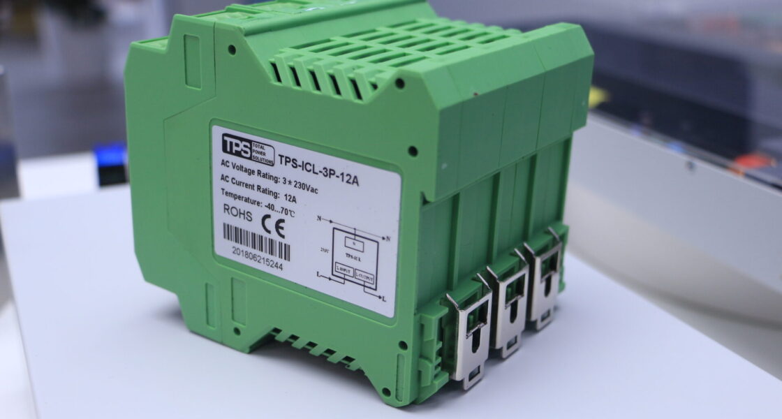
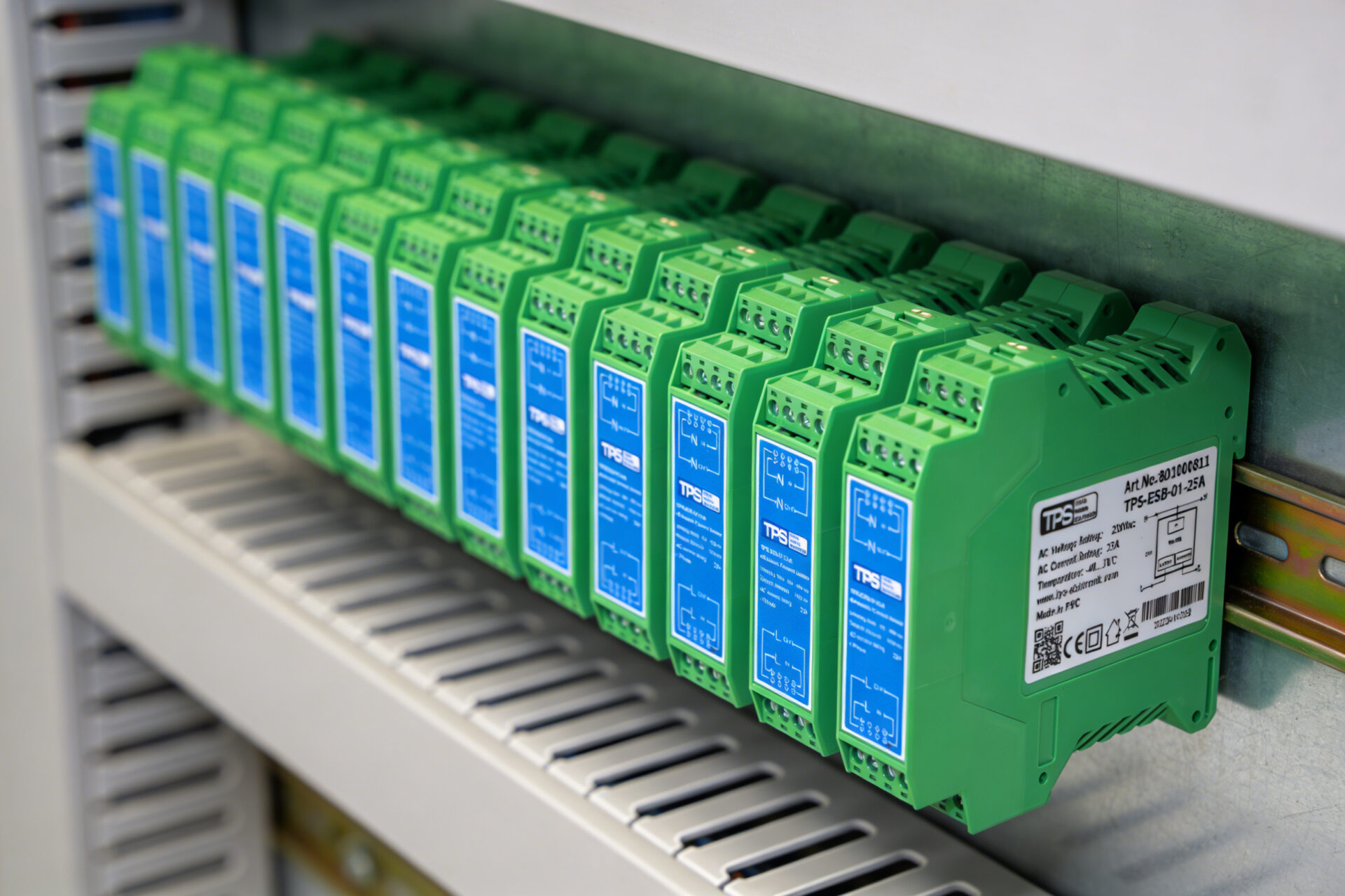
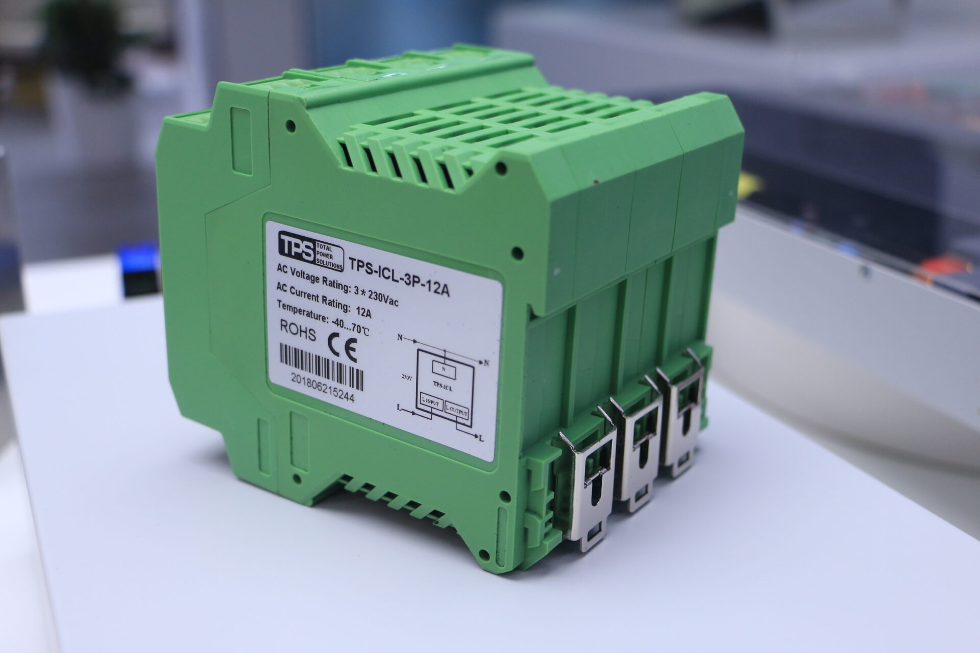
4. DIN Rail Mounted Inrush Current Limiters: The Modular Approach
For centralized power distribution in industrial panels, building automation, and machinery, DIN TS35 Mount Limiter modules are extremely popular. These current limiting modules snap onto standard 35 mm DIN rails (TS35) and provide a compact, maintenance‑free way to protect multiple circuits. They often combine peak current protection, current surge suppression, and even EMC compliant filtering in one unit. Such modules are available for a wide range of voltages and currents, making them a wide range inrush limiter solution for global applications.
The DIN rail format offers several practical benefits:
- Easy installation: Modules simply clip onto the rail without tools, reducing labor time.
- Space efficiency: Slim designs (e.g., 23 mm width) allow high density in control cabinets.
- Standardized wiring: Screw terminals accommodate various wire sizes, from 24‑16 AWG for control circuits to 16‑12 AWG for power circuits.
- Modular scalability: Additional limiters can be added as system requirements grow.
IP20 rating (finger safe) ensures safe handling during installation and maintenance when mounted inside enclosures. Cooling is typically by natural convection, eliminating the need for fans that could fail or require maintenance.
5. Key Performance Parameters of Modern Inrush Current Limiters
When evaluating a current limiting module for your application, several key specifications determine its suitability. High‑quality industrial inrush limiters typically share common performance characteristics derived from real‑world requirements.
5.1 Peak Current Limiting Capability
The peak current protection capability is perhaps the most critical parameter. Many modern current limiting devices are designed to limit inrush peaks to approximately 45 A for durations of 100‑500 ms. This window is carefully chosen: it is long enough to allow bulk capacitors to charge fully or transformer inrush to decay, yet short enough to prevent undue stress on upstream protection devices. The 45 A figure is a practical balance—high enough to accommodate most industrial loads, yet low enough to prevent nuisance tripping of standard circuit breakers.
5.2 Repeat Interval
Another essential parameter is the repeat interval—the minimum time required between power cycles before the limiter can effectively suppress another surge. For bypass relay designs, this interval can be as short as 1000 ms (1 second), enabling rapid cycling without compromising protection. This is particularly valuable in applications like UPS inrush current limiters, where automatic transfer switches may reconnect power quickly after an outage, or in testing equipment that undergoes frequent power cycling.
5.3 Environmental Ratings
Environmental robustness is equally important. Premium current limiting modules are rated for operation from -40°C to 70°C, with storage capabilities extending to -40°C to 85°C. This wide temperature range ensures reliable performance in both unheated industrial facilities and warm control cabinets. Additionally, humidity tolerance (10‑95% RH non‑condensing) and altitude ratings (up to 2000 m) guarantee consistent operation across diverse installation sites.
5.4 Safety Certifications and Compliance
For any overcurrent protection device used in industrial or commercial settings, compliance with international safety standards is non‑negotiable. Reputable inrush current limiters carry certifications such as EN62368‑1 (the successor to EN60950‑1 for IT and audio/video equipment) and EN61000‑3‑2 for harmonic current emissions. These certifications ensure that the device itself does not become a source of electromagnetic interference—hence the term EMC compliant limiter—and that it provides reliable protection under fault conditions.
Many current limiting modules also meet the requirements of CE and RoHS directives, confirming their suitability for the European market and restriction of hazardous substances. With mean time between failures (MTBF) ratings often exceeding 300,000 hours, these devices are designed for decades of trouble‑free service.
6. Application Areas for Inrush Current Limiters
Inrush current limiters are used wherever capacitive or inductive loads are switched. Below are the primary application areas, each with specific requirements.
6.1 Industrial Inrush Limiter for Machinery
Industrial equipment such as large motors, conveyors, and compressors draw high start up current. An industrial inrush limiter ensures that branch circuit breakers do not trip during startup, improving productivity. It also protects contactors and motor starters from excessive current, extending their lifespan.
6.2 HVAC Inrush Limiter
Heating, ventilation, and air conditioning systems contain motors and compressors that need drive inrush protection. HVAC inrush limiters are often installed in outdoor units to handle the high locked‑rotor current. They also protect the control circuits from voltage sags caused by compressor startup.
6.3 Lighting System Protection
LED drivers and fluorescent ballasts have capacitive inputs that cause inrush. Lighting system protection modules prevent nuisance tripping of lighting circuit breakers and extend driver life. In large commercial buildings, multiple lighting circuits can benefit from centralized current limiting modules.
6.4 UPS Inrush Current Limiter
Uninterruptible power supplies must handle the inrush of downstream equipment when transferring to battery or during restart. A UPS inrush current limiter built into the UPS output or as an external module ensures stable operation. It prevents the UPS from going into overload mode when power is restored to multiple devices simultaneously.
6.5 Drive Inrush Protection for Variable Frequency Drives
VFDs contain large DC‑link capacitors. Drive inrush protection limits the charging current, preventing input rectifier damage and extending drive life. Many VFD manufacturers recommend external inrush limiters for installations with weak supply networks.
6.6 AC Supply Protection in Power Distribution
In data centers, hospitals, and manufacturing plants, AC supply protection using current limiting modules safeguards critical loads. The DIN rail format allows easy integration into existing panels. For three‑phase systems, dedicated three‑phase current limiting modules ensure balanced protection across all phases.
7. Selecting the Right Inrush Current Limiter
Selecting an inrush current limiter involves matching the device’s specifications to your load characteristics. Follow this step‑by‑step approach.
7.1 Define Load Parameters
- Steady‑state current (IRMS): Choose a limiter rated for at least this current. Common ratings include 12 A, 16 A, and 25 A.
- Maximum allowable inrush peak: Ensure the limiter’s peak current capability (e.g., 45 A) is below the trip threshold of your upstream breaker.
- Input voltage and frequency: Match the limiter’s voltage range (e.g., 207‑253 VAC for single‑phase, 360‑440 VAC for three‑phase) to your supply.
- Ambient temperature range: Verify the limiter’s operating temperature covers your installation environment.
- Physical space: If panel space is limited, look for a compact inrush limiter with narrow width (e.g., 23 mm).
- Switching frequency: For frequent on‑off cycles, a bypass relay type is essential to avoid cool‑down delays.
7.2 Choose Technology Type
For low‑power, infrequent switching, an NTC thermistor alone may suffice. When applications involve higher power or frequent on/off cycles, a bypass relay type is recommended for maintenance‑free operation. Three‑phase loads, meanwhile, require a dedicated three‑phase module.
7.3 Verify Environmental and Safety Ratings
Check operating temperature, humidity, altitude, and required safety certifications. Ensure the product meets the standards for your region (CE, UL, etc.).
7.4 Consider Voltage Range
If your equipment will be used in multiple countries, select a wide range inrush limiter that accepts, for example, 90‑264 VAC. However, for fixed installations, a narrower range like 207‑253 VAC is sufficient and often more cost‑effective.
8. Installation and Handling Guidelines
Proper installation is critical for safety and performance. Always follow the manufacturer’s instructions:
- Disconnect the external AC isolator (fuse) before installation.
- Use an isolated screwdriver to prevent accidental shorts.
- Mount on DIN rail TS35 (vertical orientation) as specified.
- Ensure adequate ventilation for convection cooling; do not cover the module.
- Observe wire size specifications: 16‑12 AWG for higher current models, 24‑16 AWG for lower current variants.
- Tighten terminals to the recommended torque to ensure low resistance connections.
IP20 products are protected against solid objects larger than 12 mm but not water—suitable for indoor panels only. Do not install in wet locations.
9. Frequently Asked Questions (FAQ)
Q: What is the difference between inrush current and start up current?
A: They are synonymous. Both refer to the initial surge when power is applied.
Q: Can an NTC thermistor be used as a stand‑alone inrush current limiter?
A: Yes, for many applications. However, it requires cool‑down time and dissipates power continuously. A bypass relay design eliminates these drawbacks.
Q: What does the current limiter symbol look like on a schematic?
A: For an NTC thermistor, it is a resistor with a diagonal arrow and “t°”. For an active limiter, it may be a rectangle with “ICL” or a current source symbol.
Q: Are these limiters maintenance free?
A: Bypass relay types are maintenance free because the relay eliminates continuous power dissipation in the thermistor, and there are no wear‑out mechanisms under normal use. Standalone NTC thermistors may degrade over many cycles but are generally considered maintenance‑free as well (no moving parts).
Q: What is a DIN TS35 Mount Limiter?
A: It is an inrush current limiter packaged in a housing that snaps onto a standard 35 mm DIN rail (TS35). These modules are common in industrial control panels and power distribution systems.
Q: Can I use a single‑phase limiter on a three‑phase system?
A: Not directly. For three‑phase loads, use a three‑phase current limiting module, which limits inrush on all phases simultaneously and ensures balanced protection.
Q: What is a wide range inrush limiter?
A: It is a limiter designed to accept a broad input voltage range, such as 90‑264 VAC, making it suitable for global applications where mains voltage varies.
10. Future Trends in Inrush Current Limiting
As power electronics evolve, so do inrush limiting techniques. Digital control, wide bandgap semiconductors (GaN, SiC), and smart diagnostics are entering the market. Future current limiting devices may communicate with building management systems to report health and predict failures. However, for the vast majority of today’s applications, proven technologies like the bypass relay offer the best balance of cost, reliability, and performance.
11. Conclusion
Inrush current is an unavoidable phenomenon in electrical systems, but its damaging effects can be effectively mitigated with the right current limiting device. From simple NTC thermistors to advanced DIN rail mounted modules with integrated bypass relays, there is a solution for every application. By understanding what is inrush current, evaluating your load requirements, and selecting an appropriate inrush current limiter, you can ensure reliable operation, protect downstream equipment, and reduce downtime.
For more information about DIN TS35 Mount Limiter products, including standard inrush limiter models and wide range variants, consult technical datasheets or contact your supplier. Remember that proper selection and installation are key to achieving long‑term, maintenance‑free performance.


