
Key Takeaways
- The TPS-ICL-3P series from TPS elektronik, a specialized 3 phase inrush current limiter (ICL), offers a robust solution with a 25A rated current, IP20 protection, and a wide operating temperature range of -40℃ to 70℃.
-
By implementing a “front-end current limiting + back-end protection” two-stage scheme with the TPS-ICL-3P series, system designers can effectively mitigate inrush current and improve inverter stability and grid-connection behaviour.
-
With its compact housing, low profile and narrow width, the TPS-ICL-3P series is well suited for limited-space applications in outdoor PV power station control cabinets.
-
The series supports high-density installation and crowded panels by combining industrial-grade reliability with a miniature footprint for both industrial and commercial applications.
-
Understanding what inrush current is and how an inrush current limiter works is essential for optimizing PV inverter performance and service life in harsh outdoor environments.
The global shift toward renewable energy is driving rapid growth in photovoltaic (PV) systems. Small-scale 10–30 kW inverters have become the workhorses of residential, commercial and small industrial installations. These inverters convert DC power from solar modules into AC power compatible with the 3-phase 400 VAC grid.
However, a persistent challenge affects their reliable operation: inrush current during startup and grid connection.
What Is Inrush Current – and Why Is It a Problem?
Inrush current (also called inrush surge current) is the brief, but very high, current that flows when an electrical device is switched on or connected to a power source. In PV inverters, this effect is mainly caused by the charging of large input capacitors on the DC bus.
These capacitors stabilize the DC bus voltage. When the inverter connects to the grid or powers on, the capacitors are initially discharged and behave almost like a short circuit. As they charge to their rated voltage, a surge of current flows until they reach steady state. For 10–30 kW inverters, this inrush current can reach 10–20 times the rated operating current (for example 250–500 A for a 25 A inverter), typically for microseconds to milliseconds.
AC Inrush Current in 3-Phase Systems
In 3-phase 400 VAC systems, inrush current behaviour is more complex than in single-phase applications. Ideally, current is balanced across all three phases. In practice, phase imbalances, voltage transients or asymmetric capacitor charging can lead to unbalanced inrush currents.
The consequences include:
-
Disproportionate stress on individual phases
-
Increased risk of component failure
-
False tripping of protective devices
-
Disrupted inverter operation and grid-connection issues
Consequences of Unmanaged Inrush Current
If inrush current is not controlled, typical effects include:
-
Frequent restarts
Inverters use overcurrent protection (OCP) to shut down under excessive current. Inrush spikes can trigger this protection, causing repeated restarts and reducing energy yield. -
Accelerated component wear
Repeated inrush events stress capacitors, relays and semiconductor devices (e.g. IGBTs), shortening their service life and increasing maintenance costs. -
Grid compliance problems
High inrush currents can cause voltage dips or harmonics on the grid. This may conflict with interconnection standards and lead to restrictions or complaints from grid operators. -
Safety risks
Extreme current spikes can generate local overheating, potentially leading to insulation damage or, in rare cases, fire hazards in confined control cabinets.
The Role of Inrush Current Limiters (ICLs) in PV Inverters
An inrush current limiter (ICL) – also referred to as a starting current limiter – is a device that limits transient inrush currents during startup so the system can reach steady state safely. For 3-phase applications such as PV inverters, a dedicated 3-phase inrush current limiter is usually required, as it must handle current surges simultaneously on all three phases.
Limitations of Traditional Methods
Conventional inrush current mitigation approaches include:
-
Series resistors
They limit inrush current but dissipate substantial power as heat, reducing efficiency and often requiring large heat sinks. -
NTC thermistors
They self-regulate to a lower resistance when warm, but have slower response times, are sensitive to ambient temperature and degrade over many cycles. This makes them less suitable for high-power systems that can start and stop multiple times per day (e.g. due to cloud cover or grid events).
Modern Inrush Current Limiters
Modern ICLs, such as the TPS-ICL-3P series from TPS elektronik, are designed to:
-
Provide robust current limiting during startup
-
Minimize power loss during normal operation
-
Support frequent switching cycles
In simple terms, an ICL introduces a controlled impedance when the system is energized. It limits the rate of current rise during the inrush phase and then transitions to a very low impedance so that normal current can flow with minimal losses.
For 3-phase 400 VAC PV inverters, an ideal ICL should provide:
-
3-phase compatibility with balanced current limiting across all phases
-
High current handling capability (typ. up to 500 A peak in this power class)
-
Wide temperature range for harsh outdoor conditions
-
Compact design for limited-space control cabinets
-
Compliance support for relevant surge and interconnection standards
TPS-ICL-3P Series: A High-Reliability 3-Phase Inrush Current Limiter
TPS elektronik has developed the TPS-ICL-3P series specifically to address inrush current challenges in 10–30 kW 3-phase PV inverters. The series combines robust performance with a compact form factor tailored for space-constrained control cabinets.
Key Features and Specifications
-
Rated current: 25 A, matching typical 10–30 kW inverter input ratings
-
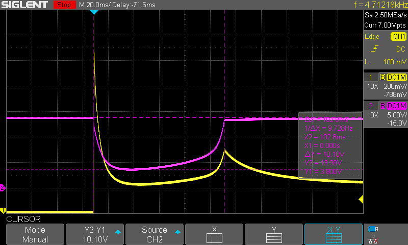
Inrush current handling: peak inrush currents can be limited to ≤ 100 A (depending on configuration), helping keep currents within the safe operating range of inverter components
-
Operating temperature range: −40 ℃ to 70 ℃ for reliable performance in extreme climates
-
Protection rating: IP20, providing finger-safe protection against solid objects ≥ 12 mm while allowing airflow for cooling
-
Fast response: response time < 1 ms during inrush events
The TPS-ICL-3P series is designed as a compact, low-profile, narrow-width device with a small footprint. This makes it suitable for:
-
Limited-space applications
-
Crowded control cabinets
-
High-density installations
Durability and Service Life
The series is built using materials and components selected for resistance to:
-
Thermal cycling
-
Vibration
-
Humidity
Solid-state design and the absence of moving parts help minimise mechanical wear. This supports a long service life and is aligned with the typical lifetime expectations of PV systems.
Two-Stage Protection: Front-End Limiting + Back-End Protection
While a high-quality ICL is essential, optimal protection for PV inverters is achieved with a holistic, two-stage concept:
Stage 1 – Front-end current limiting with TPS-ICL-3P
Stage 2 – Back-end protection for residual surges and long-term stress
Stage 1: TPS-ICL-3P at the 3-Phase 400 VAC Input
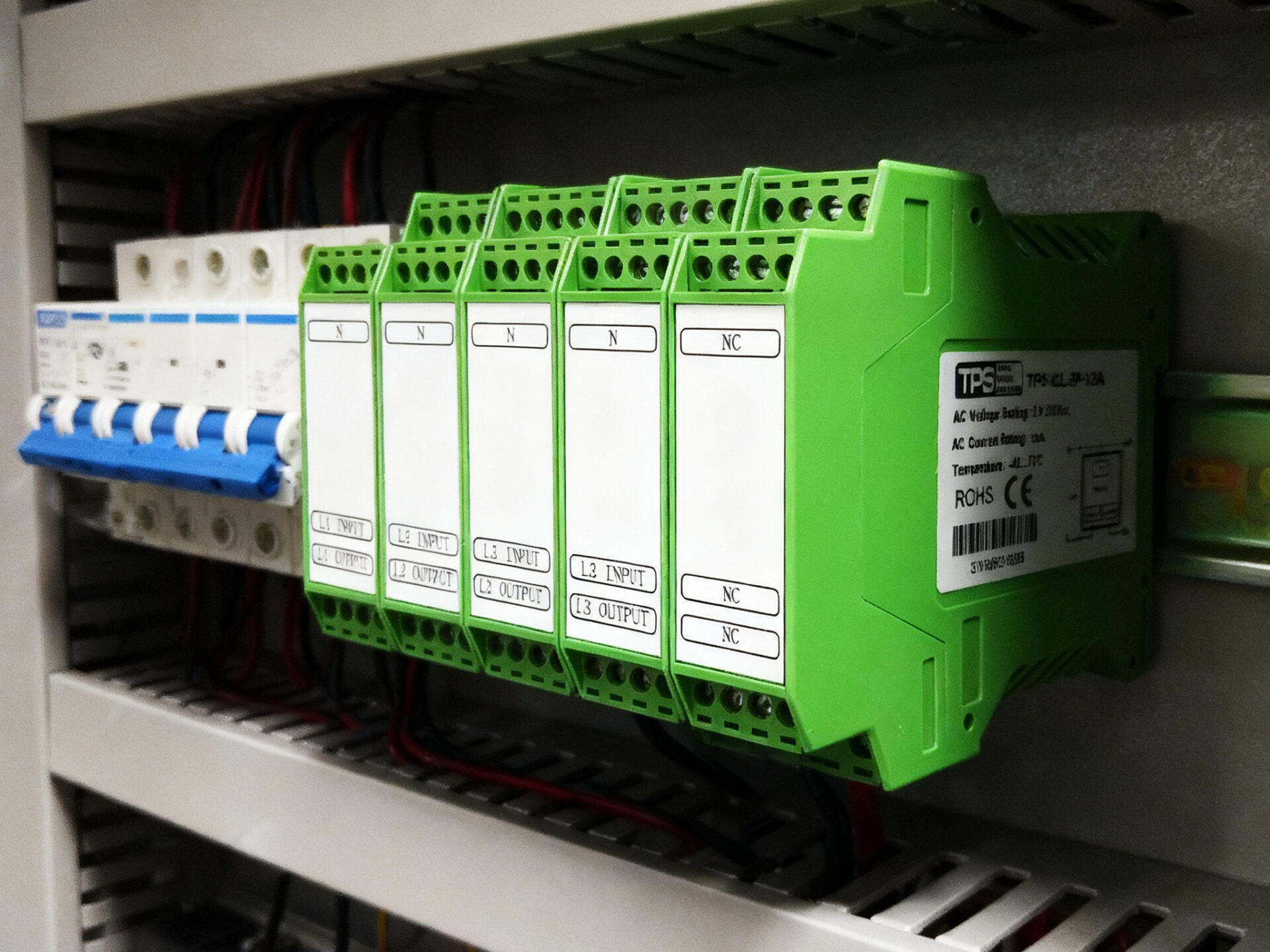
The TPS-ICL-3P is installed at the inverter’s 3-phase 400 VAC input, typically after the main disconnect switch.
Operating principle:
-
Startup phase
When the inverter energizes, the TPS-ICL-3P detects the rapid current increase and introduces a controlled impedance. This limits the inrush to a defined level (for example 2–3 times the rated current) and slows capacitor charging. -
Steady-state transition
After the capacitors are charged (within milliseconds), the device transitions to a very low impedance so that the full rated current can flow with minimal power loss (typically ≤ 0.5 W per phase). -
3-phase balancing
The ICL is designed to achieve balanced current limiting across all three phases, which is especially beneficial under slightly unbalanced grid conditions.
This front-end limiting helps avoid triggering the inverter’s OCP during startup and reduces electrical stress on input capacitors, relays and semiconductors.
Stage 2: Back-End Protection
Downstream of the TPS-ICL-3P, additional components address residual surges and long-term effects:
-
Surge Protective Devices (SPDs) to clamp voltage transients (e.g. lightning, grid switching)
-
Thermal overload relays as backup protection against sustained overcurrents
-
EMI filters to reduce electromagnetic interference and support EMC compliance (e.g. EN 61000-6-3)
The combination of front-end inrush limiting and back-end surge and overload protection provides a comprehensive, layered protection scheme for the inverter.
Space Efficiency: Designed for Limited-Space Applications
Outdoor PV control cabinets are typically compact and densely populated with inverters, breakers, meters and communication modules. Space efficiency is therefore a key selection criterion for all components.
The TPS-ICL-3P series addresses this by offering:
-
Low profile housing (typical height ≤ 30 mm)
-
Narrow width per phase (≤ 45 mm)
-
Slim depth (≤ 60 mm) for shallow cabinets
This makes the series suitable for:
-
Limited-space applications where every millimetre counts
-
High-density installations with many components in close proximity
-
Retrofits of existing PV systems with already crowded cabinets
DIN-rail mounting (standard in industrial control cabinets) allows quick installation in various orientations and simplifies integration into new and existing layouts.
Compared with traditional inrush protection solutions that require bulky heat sinks or separate enclosures, the TPS-ICL-3P can significantly reduce the space required for inrush protection
Reliability in Harsh Environments
PV inverters are often installed in challenging environments – from cold northern climates to hot desert regions. The TPS-ICL-3P series is engineered for these conditions.
Key aspects include:
-
Wide operating temperature range (−40 ℃ to 70 ℃)
High-temperature-resistant plastics and metal alloys maintain mechanical and electrical properties across the range. Components are rated for repeated thermal cycling to reduce risks such as solder joint fatigue. -
IP20 protection
While the outer cabinet typically provides weather protection, IP20 helps prevent accidental contact and reduces the risk of faults caused by larger solid foreign objects, while maintaining ventilation. -
Vibration resistance
PV cabinets can be mounted on poles, rooftops or ground structures that are exposed to wind-induced vibrations. The TPS-ICL-3P series is designed and tested according to relevant vibration standards (e.g. IEC 60068-2-6) to ensure stable operation in such environments.
Compliance and Standard Support
Grid-connection and safety standards define strict requirements for inrush behaviour, surge immunity and protection. The TPS-ICL-3P series is designed to support compliance with key international and regional standards, for example:
-
IEC 61000-4-5 – surge immunity for electrical equipment
-
IEEE 1547 – interconnection of distributed energy resources with the grid
-
EN 62109 – safety of power converters for use in PV power systems
Depending on the specific system design and region, certification by notified bodies such as TÜV, UL and CE can be achieved as part of the overall inverter and system approval process. This helps reduce time-to-market for manufacturers and simplifies homologation for system integrators.
(Note: always verify the current certification status of the specific product variant before making binding claims in datasheets or marketing material.)
Real-World Example Applications
Case Study 1: 20 kW Commercial PV System in Southern Europe
A 20 kW commercial PV system in Spain experienced frequent inverter restarts – up to five times per day during peak sunshine hours. The original installation used a 3-phase 400 VAC inverter without dedicated inrush protection. Measured inrush peaks were around 350 A during grid connection, regularly triggering the inverter’s OCP and reducing annual energy yield.
After integrating the TPS-ICL-3P series as part of a two-stage protection concept, measured inrush peaks were reduced to around 80 A, clearly below the OCP threshold in this installation. The number of restarts dropped significantly and the operator reported an increase in effective energy yield. The compact footprint allowed installation in the existing control cabinet without major mechanical changes.
Case Study 2: 30 kW Industrial PV System in Northern Europe
A 30 kW industrial PV system in Sweden initially failed to meet local grid operator requirements, as inrush current exceeded the specified 120 A limit for 25 A equipment. The cold climate (down to −25 ℃ in winter) also raised concerns about long-term reliability.
After installing the TPS-ICL-3P series, inrush peaks were reduced to approx. 95 A in this system, bringing the installation within the operator’s limits. The wide operating temperature range helped ensure reliable performance through the winter season, and the low profile housing made it possible to integrate the device into an already densely packed cabinet.
Choosing the Right Inrush Current Limiter: Key Criteria
When selecting an inrush current limiter for a 3-phase PV inverter, consider:
-
Phase compatibility
Use a dedicated 3-phase inrush current limiter rather than adapting single-phase devices. The TPS-ICL-3P is engineered for balanced 3-phase operation. -
Rated current
Match the limiter’s rated current to the inverter’s operating current (e.g. 25 A for many 10–30 kW inverters). Oversizing can weaken the limiting effect; undersizing can lead to overheating. -
Inrush handling capability
Check that the limiter can handle the expected peak inrush current (often 10–20× the rated current). The TPS-ICL-3P is designed for peaks up to 500 A (depending on configuration). -
Temperature range
Choose a device with an operating range that covers the actual cabinet temperatures at the installation site. The −40 ℃ to 70 ℃ range of the TPS-ICL-3P covers most global climates. -
Space constraints
Opt for compact designs with low profile and narrow width for limited-space applications. The small footprint of the TPS-ICL-3P is well suited for crowded control cabinets. -
Standard and certification support
Ensure the device supports relevant regional and international standards and can be used within certified system designs (e.g. TÜV in Europe, UL in North America).
By taking these factors into account, engineers can select an ICL that protects the inverter effectively and integrates smoothly into the overall system.
Frequently Asked Questions (FAQs)
What is inrush current, and why is it a problem in PV inverters?
Inrush current is a short-duration current spike that occurs when a device is energized. In PV inverters it is primarily caused by the rapid charging of input capacitors and can exceed the rated current by a factor of 10 or more. If not controlled, it can trigger protective shutdowns, stress components and impact grid-connection behaviour.
What is an inrush current limiter (ICL), and how does it work?
An ICL is a device that temporarily introduces a controlled impedance into the circuit when it is switched on. It limits inrush current to a defined level and then transitions to a very low impedance in steady-state operation, so that normal current can flow with minimal power loss.
Why is a 3-phase inrush current limiter necessary for PV inverters?
3-phase PV inverters draw inrush current on all three phases. A dedicated 3-phase inrush current limiter is designed to provide balanced protection across all phases and to support compliance with grid-connection requirements.
How does the TPS-ICL-3P series fit into limited-space applications?
The TPS-ICL-3P series features a compact, low-profile, narrow-width design. This leads to a small footprint that is well suited for high-density installations and crowded PV control cabinets where space is limited.
Can the TPS-ICL-3P series operate in extreme temperatures?
Yes. The TPS-ICL-3P has an operating temperature range of −40 ℃ to 70 ℃. It is designed and tested for use in harsh outdoor environments, from cold winter conditions to hot summer climates, when installed according to the manufacturer’s guidelines.
Conclusion: TPS-ICL-3P – A Practical Solution for Small 3-Phase PV Inverters
The 10–30 kW small PV inverter segment requires robust and space-efficient solutions to handle inrush surge currents at 3-phase 400 VAC inputs. The TPS-ICL-3P series from TPS elektronik provides a targeted approach to this challenge by combining high-performance 3-phase inrush limiting with a compact design for limited-space applications.
By implementing a “front-end current limiting + back-end protection” two-stage scheme, PV system designers can significantly reduce unnecessary inverter restarts, ease component stress and support compliance with grid and safety standards. The 25 A rating, IP20 protection and −40 ℃ to 70 ℃ operating range make the TPS-ICL-3P suitable for a wide range of environments, while its compact footprint simplifies integration into crowded control cabinets.
As PV deployment continues to grow, the reliability of inverters remains a key factor in project performance. The TPS-ICL-3P series offers a technically sound, space-saving inrush current limiting solution for small 3-phase PV inverters – helping system integrators, manufacturers and operators improve availability and reduce downtime without compromising on cabinet space.
Discover the TPS-ICL-3P inrush current limiter series for 3-phase 400 V AC inputs, available in 12 A and 25 A versions for PV inverters and industrial control cabinets.
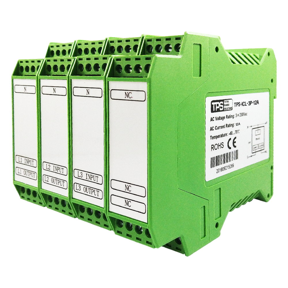
TPS-ICL-3P-12A
3-phase inrush current limiter, 12 A. Ideal for small 3-phase PV inverters and compact industrial control panels.
View product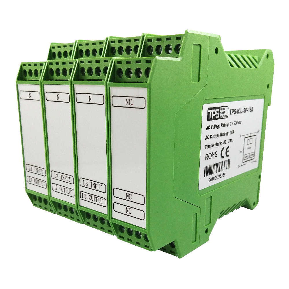
TPS-ICL-3P-16A
3-phase inrush current limiter, 16 A. Ideal for protecting motors, transformers, and other three-phase inductive/capacitive loads from damaging inrush currents.
View product
TPS-ICL-3P-25A
3-phase inrush current limiter, 25 A. Designed for 10–30 kW PV inverters and demanding industrial applications.
View product

