Key Takeaways
- Correct DIN rail mounting, spacing, and orientation support heat dissipation and compliance with applicable safety requirements.
- Proper wire sizing and termination help reduce voltage drop, overheating, and premature component stress in 12 V and 24 V DC systems.
- Grounding, surge protection, and isolation complement built-in protection features such as overvoltage and overtemperature protection.
- Thoughtful component placement improves thermal behavior, EMC performance, and maintenance access.
- Structured testing and documentation support long-term operational reliability.
Introduction
Power-related failures in industrial control systems or LED installations are often linked to installation practices rather than product defects. Even high-quality DIN rail power supplies can only perform as specified when correctly mounted and wired.
This guide provides structured, field-oriented guidance for installing AC/DC DIN rail power supplies in industrial and commercial environments. It bridges the gap between datasheet specifications and practical implementation.
1. Pre-Installation Planning and Safety
1.1 Safety Precautions
Before installation:
- Isolate all power sources and verify absence of voltage using a certified tester.
- Apply lockout-tagout (LOTO) procedures.
- Identify secondary or back-fed voltage sources.
For line-voltage AC inputs, additional PPE (voltage-rated gloves, face shield, flame-resistant clothing) may be required depending on local regulations. Always follow applicable national electrical codes and workplace safety rules.
1.2 Selecting the Appropriate DIN Rail Power Supply
Selection should go beyond nominal voltage and current.
Key Selection Criteria
Voltage Stability Requirements
- 12 V DC: ±5% often acceptable for relays and solenoids.
- 24 V DC: ±2% may be required for sensors and controllers.
Current Requirements
- Calculate steady-state load.
- Include inrush currents.
- Apply an engineering safety margin.
Environmental Conditions
- Consider ambient temperature.
- Apply manufacturer derating guidelines above 40–50 °C.
- Ensure airflow for convection-cooled designs.
Protection Features
- Verify built-in protections:
- Overvoltage protection (OVP)
- Overcurrent protection
- Overtemperature protection
Certification Requirements
- CE marking for EU market access.
- Additional certifications depending on industry.
For sensitive electronics (e.g., 5 V DC loads), review ripple and noise specifications. For LED applications, confirm constant voltage vs. constant current compatibility.
Warranty duration may provide general insight into design margins, but it should not replace technical evaluation.
1.3 Tools and Materials
Essential Tools
- DIN rail cutter or fine-tooth saw
- Wire strippers (multi-gauge)
- Ferrule crimping tool
- Calibrated torque screwdriver (0.5–2.5 Nm typical range)
- Digital multimeter (True RMS)
- Insulation resistance tester
- Cable cutter
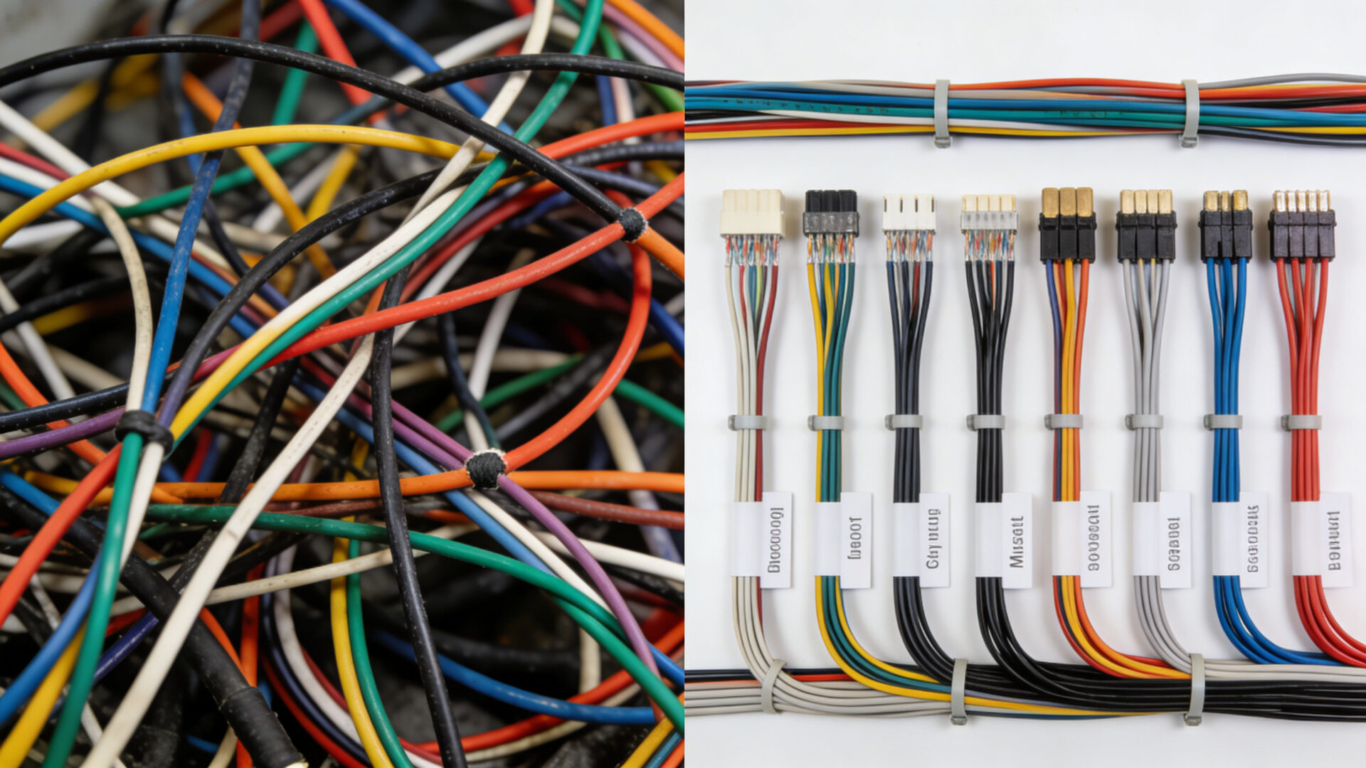
- Labeling system
Required Materials
- TS-35 DIN rail (7.5 mm or 15 mm height)
- Appropriately rated copper conductors
- Ferrules for stranded wires
- Circuit breakers or fuses
- End brackets and separators
- Cable management accessories
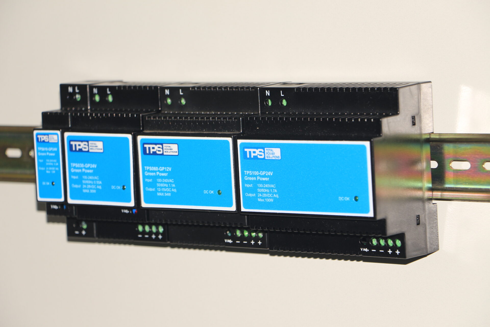
2. DIN Rail Mounting Best Practices
2.1 DIN Rail Selection
The TS-35 DIN rail (35 mm width) is standard.
- 7.5 mm height: typical control cabinet installations
- 15 mm height: higher rigidity for heavy devices
Allow sufficient clearance for ventilation:
- Typically 50 mm above and below (check manufacturer data)
- Minimum spacing between adjacent units (often 10–25 mm depending on power rating)
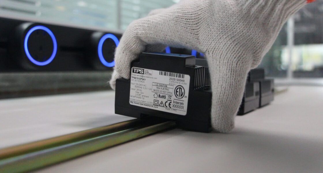
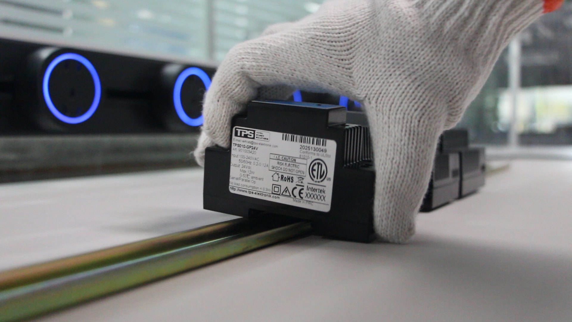
2.2 Mounting Procedure
- Hook the upper part of the power supply onto the DIN rail.
- Pivot downward until the locking mechanism clicks.
- Verify secure engagement.
- Position with required spacing.
Arrange components logically:
- Input protection → Power supply → Output distribution
Keep distance from major heat sources (e.g., drives, transformers).
2.3 Thermal Management
For multiple units:
- <100 W: typically 10 mm spacing
- 100–240 W: approx. 15 mm
- Higher power: 25 mm or as specified
Install units to support natural convection (vertical airflow).
In forced-air cabinets, align with airflow direction.
Monitor cabinet ambient temperature in high-density installations.
3. Wiring Practices
3.1 AC Input Wiring
Verification Steps
- Confirm input voltage range.
- Measure actual supply voltage under load conditions.
Protection Strategy
- Install a circuit breaker or fuse close to the supply.
- Use surge protective devices (SPD) where required.
- Ensure accessible disconnect means.
Wire Sizing
- Size according to:
- Ampacity
- Permissible voltage drop (typically ≤3%)
- Use copper conductors.
- Apply ferrules for stranded wires.
- Tighten terminals to manufacturer torque specification.
- Perform a pull test after termination.
3.2 DC Output Wiring
Voltage Drop Management
Particularly critical for 12 V systems.
- Use adequately sized conductors.
- Avoid long daisy-chain wiring.
- Use star distribution for critical loads.
Output Protection
- Branch fusing recommended.
- Electronic circuit breakers for dynamic loads.
- Reverse polarity protection where applicable.
For 24 V control systems:
- Separate analog and digital supply lines.
- Use shielded cables for sensitive signals.
3.3 Grounding and Shielding
Protective Earth (PE)
- Connect metal chassis to PE.
- Use green/yellow conductor.
- Do not rely solely on DIN rail grounding.
- Verify low-impedance continuity.
Signal Grounding
- Separate safety ground and signal reference.
- Use single-point grounding for sensitive measurement circuits.
EMC Measures
- Separate power and signal cables.
- Cross at 90° if unavoidable.
- Use ferrites where required.
- Properly terminate cable shields.
4. Protection and Commissioning
4.1 Built-In Protection Features
Common integrated protections:
- Overvoltage protection (OVP)
- Overcurrent protection
- Overtemperature protection
- Short-circuit protection
Understand whether the unit:
- Latches off after fault
- Automatically restarts (“auto-recovery”)
Ensure behavior matches application safety requirements.
4.2 Commissioning Procedure
Pre-Energization
- Continuity test
- Insulation resistance test
- Torque verification
- Correct polarity check
Initial Power-Up
- Energize without load.
- Verify output voltage.
- Check status indicators.
Load Testing
- Apply load gradually (25% → 50% → 75% → 100%).
- Monitor temperature and voltage stability.
- Observe for abnormal noise or instability.
Protection Verification
- Simulate overload conditions.
- Verify recovery behavior.
- Document all measurements.
5. Maintenance and Reliability
Preventive Maintenance
- Visual inspection for discoloration or overheating.
- Check terminal torque periodically.
- Clean ventilation openings.
- Measure output voltage under known load.
Performance Monitoring
Track:
- Operating temperature trends
- Voltage stability
- Protection event frequency
Plan replacement proactively based on lifecycle information and application criticality.
Conclusion
DIN rail power supply performance depends not only on product design but also on correct installation, wiring, and thermal management.
By applying structured mounting practices, correct conductor sizing, proper grounding, and systematic testing, installers can support stable and predictable system behavior in industrial environments.
Professional installation practices contribute significantly to long-term operational reliability and maintainability.


