Initial Situation
A company operating in the renewable energy sector approached TPS Elektronik with a complex engineering task. The customer aimed to modernize a power conversion unit that had originally been developed more than ten years earlier. The existing design showed limitations in efficiency, thermal behavior, and operational stability, particularly when exposed to fluctuating input voltages.
The objective was to develop a buck-boost converter design capable of stable operation during both charging and discharging cycles. The customer requested technical support in buck-boost converter circuit design, including buck-boost converter design calculations and validation of relevant buck-boost converter design equations to improve overall energy conversion performance.
In addition, the legacy system relied on hard-switching power supply concepts, which led to increased thermal stress, switching noise, and reduced component lifetime. Under transient load conditions, the existing power supply on/off hard switch behavior proved inconsistent and required improvement.
Beyond power conversion, the system also required a reliable circuit protection concept. The customer requested support in circuit breaker design, including a compact miniature circuit breaker design suitable for space-constrained installations. As parts of the system were software-controlled, the scope also included the implementation of a circuit breaker design pattern in microservices to improve fault tolerance in distributed control software.
The project further required the integration of an analog integrated 2-D optical flow sensor to monitor airflow and thermal behavior inside the converter housing during operation.
TPS Elektronik Solution
TPS Elektronik delivered an end-to-end engineering solution covering concept development, simulation, hardware design, and system validation.
Converter Design and Simulation
- Development of a buck-boost converter design based on detailed modeling and simulation
- Application and verification of established buck-boost converter design equations for voltage and current regulation
- Execution of buck-boost converter design calculations to support component selection, thermal design, and switching frequency definition
- Technical support covering the complete process of how to design a buck-boost converter, from concept phase to compliance considerations
- Implementation of a DC-DC buck-boost converter design optimized for efficiency and operational stability
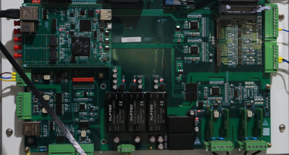
PCB Design and Integration
- Delivery of a complete buck-boost converter PCB design with optimized layout, controlled current paths, and EMI-aware routing
- Careful separation and integration of analog and digital sections to maintain signal integrity and reduce switching losses
- Integration of the analog integrated 2-D optical flow sensor for real-time airflow monitoring inside the enclosure
Power Supply and Switching Optimization
- Replacement of legacy hard-switching power supplies with a modern switching topology
- Optimization of power supply switch-on behavior through improved gate control and soft-start implementation
- Design of a robust power supply on/off hard switch solution with improved thermal management and component protection
Circuit Protection Design
- Engineering of an electronic circuit breaker design to disconnect the system in the event of overload or fault conditions
- Development of a compact miniature circuit breaker design suitable for integration within the converter housing
- Implementation of a circuit breaker design pattern in the control software and microservices architecture to reduce the risk of cascading failures
Testing and Validation
- Functional and thermal testing under defined load and operating conditions
- Verification of system behavior during dynamic load changes and simulated fault scenarios
- Validation against applicable EMC and electrical safety requirements at system level
Results
The updated system demonstrated measurable improvements compared to the legacy design:
- Improved efficiency: The new buck-boost converter design achieved a system efficiency of up to 95% under defined operating conditions
- Enhanced thermal behavior: Optimized layout and buck-boost converter PCB design reduced operating temperatures by approximately 20%
- Improved reliability: The updated switching concept reduced stress during transient events
- Compact protection: The integrated miniature circuit breaker design enabled effective protection within limited installation space
- Software robustness: The circuit breaker design pattern in microservices improved system stability during fault conditions
- Operational monitoring: The integrated optical flow sensor enabled continuous monitoring of internal airflow for thermal analysis
Conclusion
This case study illustrates TPS Elektronik’s engineering expertise in buck-boost converter design and circuit protection concepts for renewable energy applications. By combining hardware development, buck-boost converter design calculations, PCB layout optimization, and software-based protection mechanisms, TPS Elektronik supported the modernization of a complex power conversion system.
The project covered both electrical and software-related aspects, ranging from optimized power supply switching behavior to the application of circuit breaker design patterns in distributed control systems.
With experience in DC-DC buck-boost converter design, circuit protection development, and sensor integration, TPS Elektronik supports customers in developing reliable and efficient power electronics solutions tailored to industrial requirements.


