Key Takeaways
- BNC connectors are bayonet-style coaxial connectors with 50-ohm or 75-ohm impedance, using a quarter-turn locking mechanism.
- Standard 50 Ω BNC operates from DC to about 4 GHz. True 75 Ω “12G” BNC versions support SDI video up to 12 GHz; miniature HD-BNC variants can extend even higher depending on series.
- BNC stands for Bayonet Neill–Concelman, named after inventors Paul Neill and Carl Concelman.
- Available in both 50 Ω and 75 Ω versions—choose the connector to match the system impedance.
- Typically rated for ≥500 mating cycles when installed and handled properly.
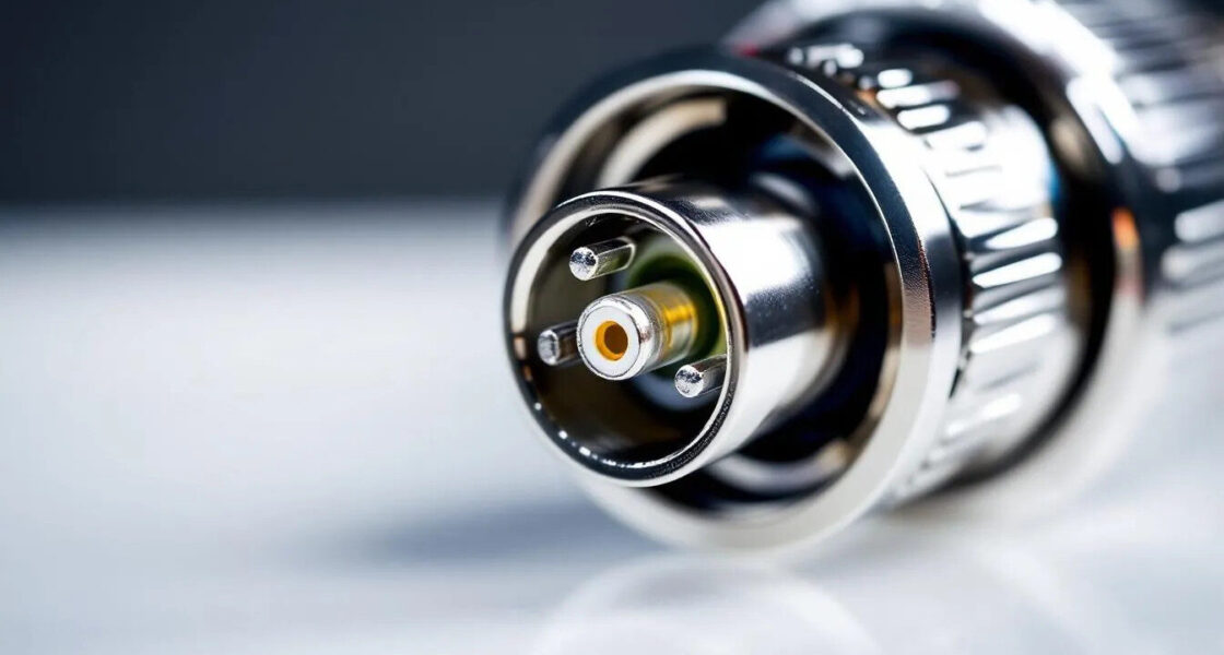
What is a BNC Connector
A
BNC connector is a compact, quick-connect radio-frequency connector for coaxial cables. The acronym “BNC” stands for
Bayonet Neill–Concelman, after inventors Paul Neill and Carl Concelman, who developed the design in the 1940s.
The key feature is the
bayonet coupling mechanism, which achieves a secure connection with a quarter-turn twist instead of a threaded interface. This enables fast, repeatable mating where frequent connect/disconnect is required.
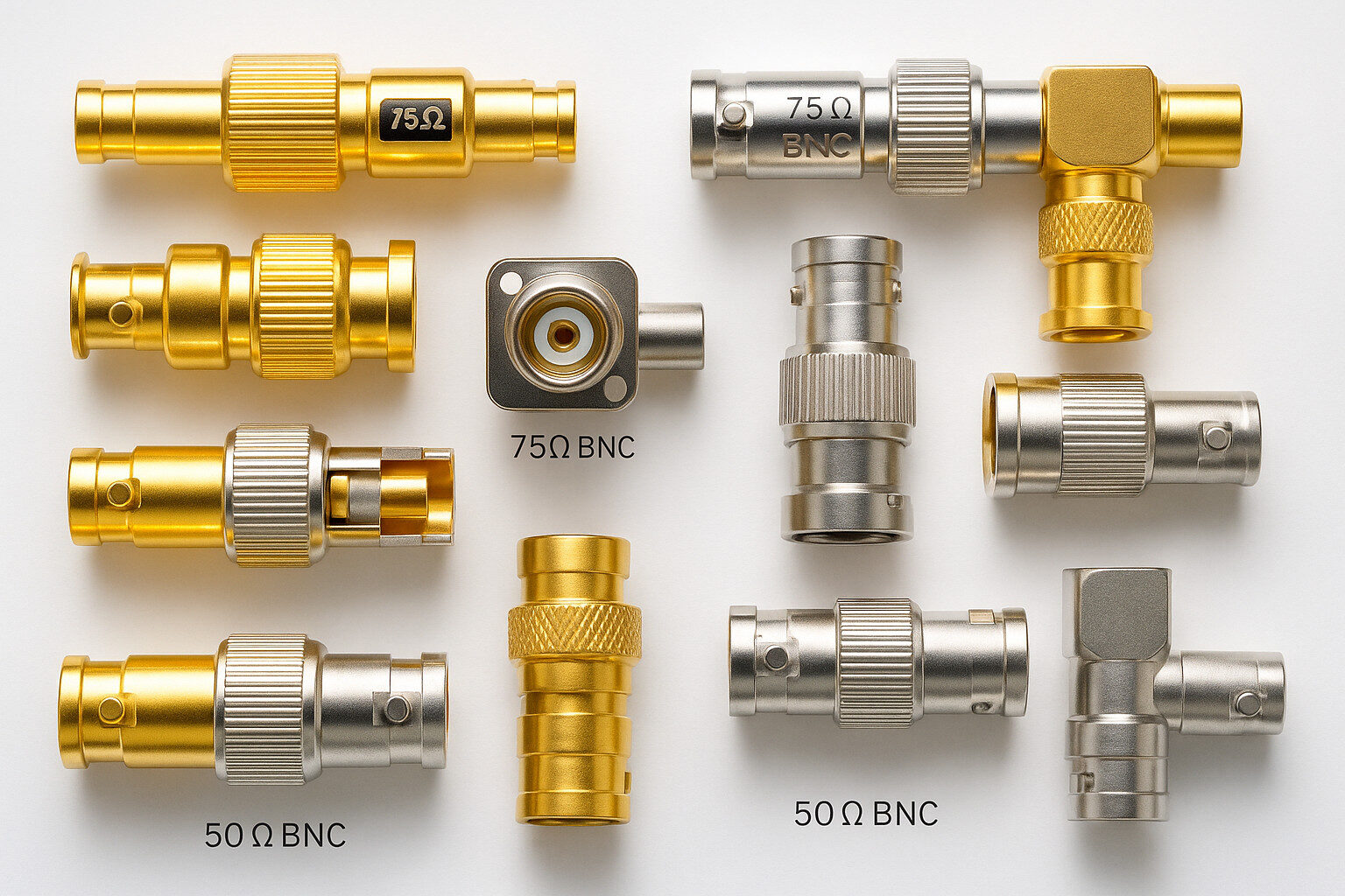
BNC connectors are available in
50 Ω and 75 Ω variants, commonly used for RF/test systems and video transmission, respectively. Impedance matching is essential to minimize reflections and preserve signal integrity.
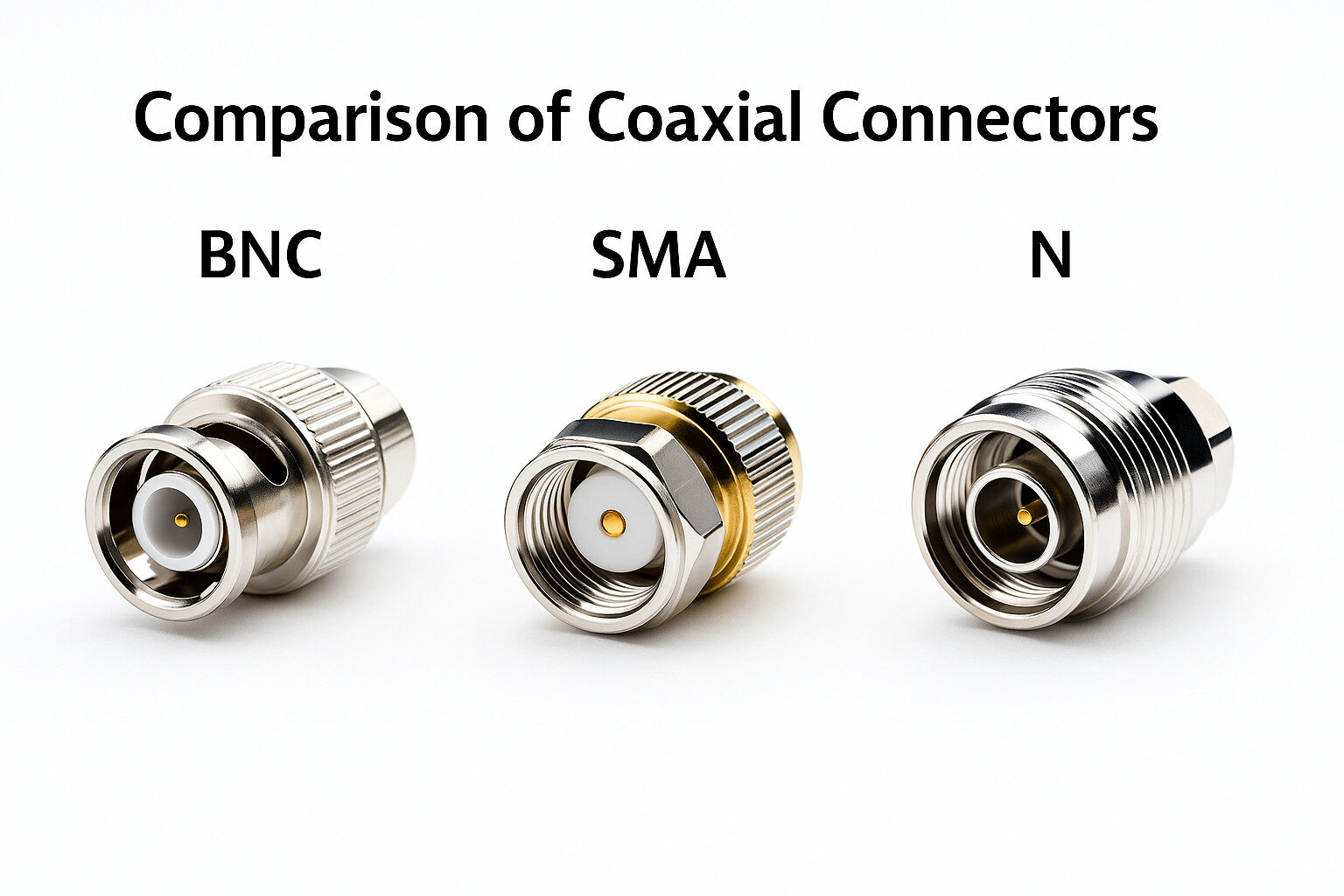
Compared with
SMA connectors—which use threads and are intended for microwave systems well above 4 GHz—BNC prioritizes speed and ease of use at lower frequencies. SMA generally offers higher-frequency performance; BNC offers faster handling within its rated band.
Most versions use a brass body with nickel plating (sometimes gold on contacts); stainless steel versions are used for
corrosion resistance and mechanical strength. The dielectric is typically PTFE.
Technical Specifications
Impedance Characteristics
- 50 Ω BNC: common for test equipment, antennas, and RF devices.
- 75 Ω BNC: used in broadcasting, CCTV, and professional video systems.
The difference is mainly in the
inner-diameter geometry of the dielectric and center-pin dimensions/tolerances.
Frequency Performance
- Standard 50 Ω BNC: DC to ~4 GHz.
- True 75 Ω “12G” BNC (video): up to 12 GHz.
- HD-BNC (miniature family, not standard-size BNC): up to ~12–18 GHz depending on series.
- VSWR: typically < 1.3:1 within the specified frequency band.
- Insertion loss: typically ~0.2 dB at 3 GHz (varies by series and gender).
Environmental and Mechanical
- Temperature range: −65 °C to +165 °C (typical PTFE-insulated ranges; verify per series).
- Voltage withstand: up to ~500 VRMS for standard BNC; higher-voltage applications use MHV/SHV families.
- Mating durability: ≥500 cycles (typical minimum).
- RF leakage/shielding: typically ≥55 dB at 3 GHz (model-dependent).
Types and Variants
Standard Configurations
- Male connector: center pin, used on cables and outputs.
- Female connector: recessed contact, common on equipment inputs.
- Available as straight or right-angle versions for tight spaces.
Panel and Bulkhead Mounting
Bulkhead connectors use a
hex nut for chassis mounting. Some offer DC isolation between shell and chassis to manage grounding and interference.
Specialized Variants
- 12G BNC (true 75 Ω): for SDI video to 12 GHz.
- HD-BNC (miniature bayonet family): higher density; up to ~12–18 GHz depending on series.
- Reverse-polarity BNC (RP-BNC): center-contact gender swapped; used where a “unique-connector” requirement applies (less common than RP-SMA/TNC).
- Twinax BNC: dual contacts for 78 Ω or 95 Ω differential signals.
- Mini-BNC: compact footprint, ~3 GHz typical.
Applications and Use Cases
Test and Measurement
Oscilloscopes, signal generators, and analyzers widely use BNC for
reliable electrical performance. The quick-connect design is ideal where
many coaxial cables must be swapped.
Video and Broadcasting
75 Ω connectors are the industry standard in CCTV, SDI broadcasting, and professional video, providing dependable,
low-loss transmission when properly matched.

RF and Communication
Amateur radios,
antennas, and many RF systems use 50 Ω BNC. The compact form factor suits portable gear.
Laboratory and Scientific
Instruments across disciplines use BNC for flexible setups.
High-quality cables with correct outer-conductor termination are essential for accurate results.
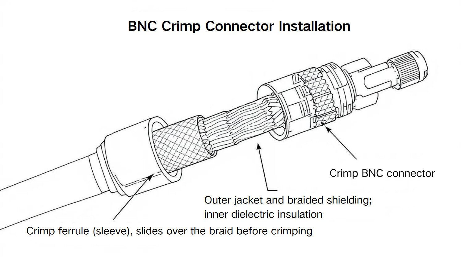
Installation and Proper Usage
Cable Preparation
For flexible coax (e.g., RG-58 or RG-59), strip the jacket to the specified lengths for your connector type (crimp, clamp, or solder). Ensure correct
outer-conductor and dielectric exposure to maintain impedance.
Quarter-Turn Locking
Align the bayonet lugs with the slots, insert, and twist ~90° until locked. Do not exceed the stop or apply excessive torque.
Maintenance
- Inspect for bent/damaged contacts or worn bayonet lugs.
- Clean gently; avoid harsh solvents.
- Use dust caps when not in use.
Compatibility and Standards
- Standardized under IEC 61169-8, MIL-STD-348, and MIL-PRF-39012.
- These standards ensure dimensional compatibility and interoperability across manufacturers.
Cable Compatibility
- RG-58 (50 Ω, RF/test).
- RG-59 (75 Ω, video).
- RG-6 (75 Ω, video/long-run SDI).
- Low-loss variants are preferred at higher frequencies or longer lengths.
Adapters
- BNC–SMA and BNC–N-type adapters enable interconnection across device families.
- Each additional interface introduces potential loss and mismatch; use only when necessary.
Advantages and Limitations
Advantages
- Fast, quarter-turn connection.
- Robust mechanical durability when installed correctly.
- Widely standardized and readily available.
- Secure coupling that resists accidental disconnection.
Limitations
- Lower maximum frequency than SMA for microwave applications.
- Larger than miniature connectors (e.g., MMCX, U.FL).
- Not intended for high-power RF; observe series-specific power limits.
Frequently Asked Questions
What does BNC stand for?
Bayonet Neill–Concelman, after its inventors.
Can I mix 50 Ω and 75 Ω connectors?
No. Impedance mismatch causes reflections and degraded signals.
How many mating cycles are possible?
Typically 500 or more, depending on quality and usage conditions.
Difference between BNC and TNC?
TNC uses a threaded interface that generally supports higher-frequency performance and provides better sealing for outdoor use; BNC mates faster with a quarter-turn bayonet.
Are BNC waterproof?
Standard versions are not. For outdoor applications, use weather-sealed BNC variants or appropriate sealing accessories.