Solar PV inverters rely on power electronics and large DC-link capacitors—two areas where uncontrolled current peaks can increase electrical stress. Inrush current limiting is often used alongside surge protection to improve robustness during start-up, restart, and post-surge recovery.
Key Takeaways
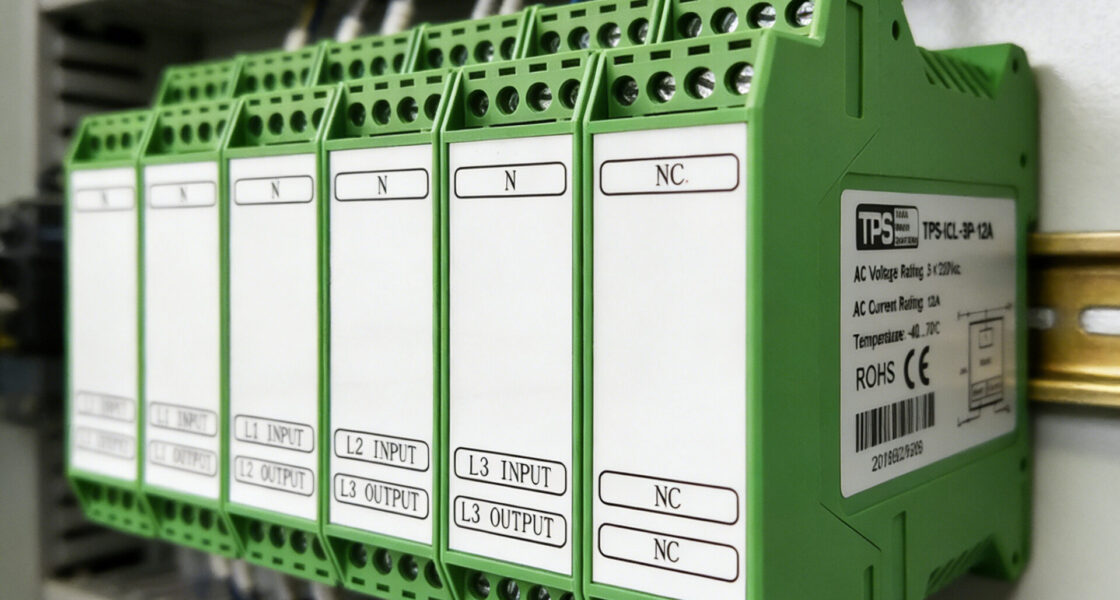
- Inrush Current Limiters help limit short-duration current surges during equipment start-up or restart, which can reduce electrical stress on solar PV components.
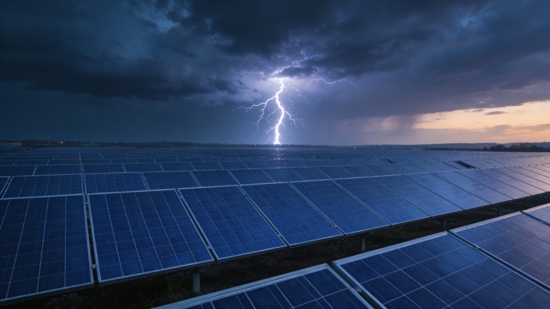
- Lightning-related surges can affect PV plants through multiple coupling paths and may not be fully addressed by surge protection devices (SPDs) alone in every scenario.
- Solid-state, non-NTC inrush limiter concepts are designed for repeatable operation and stable performance under frequent cycling and elevated ambient temperatures.
- A layered protection strategy commonly combines Type 1+2 SPDs at the AC service entrance with an active inrush current limiter near the inverter input.
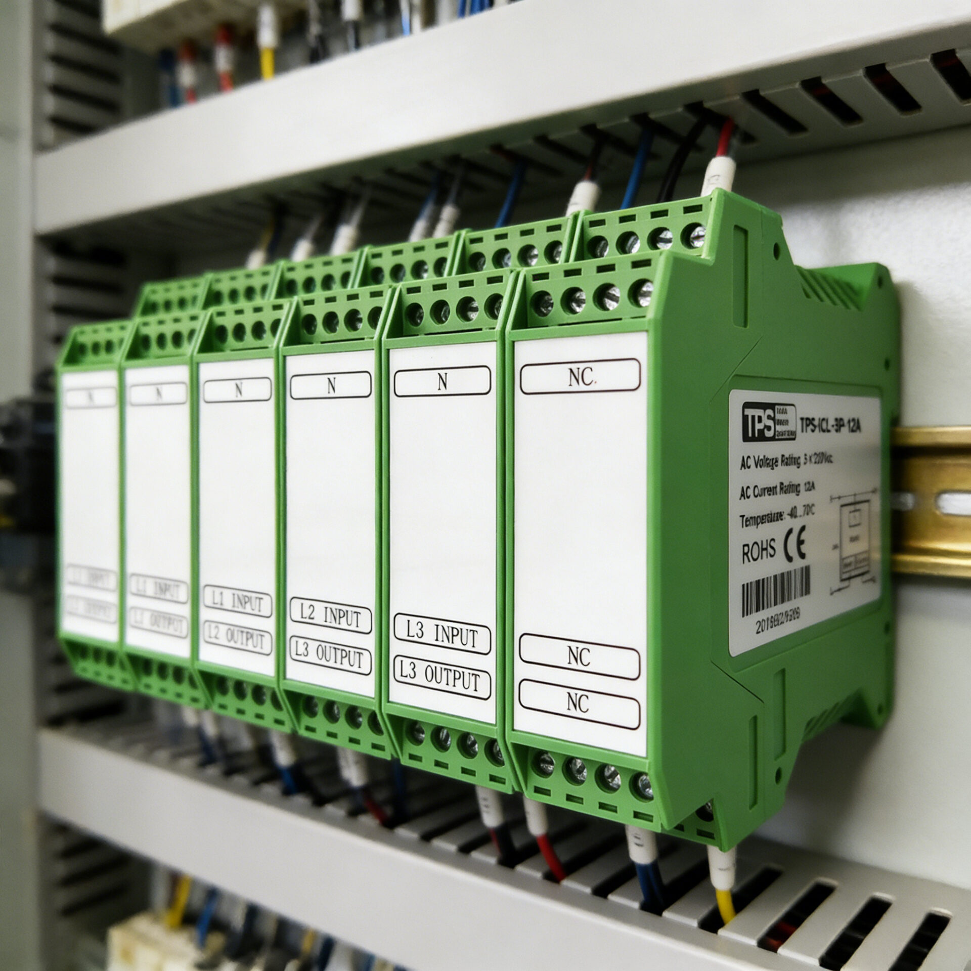
- Key selection criteria include rated current, peak current capability, DIN-rail mounting, integrated bypass mechanisms, and conformity with applicable CE and RoHS requirements.
A Practical Risk Scenario
Consider a remote utility-scale solar farm operating under normal grid conditions. A nearby thunderstorm triggers a lightning strike several hundred meters away. Although upstream SPDs limit peak voltage, part of the surge energy may propagate further into the system.
During this event or during a subsequent restart inverter input capacitors can be re-energized abruptly. This can create a short-duration but high-amplitude inrush current. If unmanaged, such current peaks may increase electrical stress on power electronic components. This illustrates why inrush current control is often considered alongside classical surge protection measures.
Inrush Current Limiting as a Second Protective Layer
This article examines the role of inrush current limiters within a broader protection concept for solar PV systems. Rather than replacing SPDs, inrush limiters typically complement surge protection by addressing current-related stress mechanisms during:
- start-up,
- restart, and
- post-surge recovery.
Scope of This Guide
The following sections:
- discuss operational limitations of traditional NTC-based inrush current limiters,
- introduce electronically controlled non-NTC alternatives, and
- outline integration concepts for solar PV inverter systems.
The aim is to support informed design decisions focused on operational reliability and system availability.
Solar PV Systems: Power Density and Sensitivity
Modern solar PV installations rely heavily on power electronics, including IGBTs and SiC MOSFETs. Large DC-link capacitors stabilize voltage and support dynamic load conditions. When energized, these capacitors draw a high initial current—commonly referred to as inrush current.
Under standard operating conditions, this current can be managed using appropriate limiting components. However, solar installations are often exposed to:
- frequent grid disturbances,
- wide ambient temperature ranges, and
- high expectations for uptime with minimal maintenance.
Conventional NTC thermistor-based limiters depend on thermal behavior. After a recent operation or interruption, the thermistor may remain warm, reducing its resistance and limiting effectiveness during a subsequent restart. This “hot-start” condition can reduce predictability in demanding applications.
Lightning and Surge Effects in PV Installations
Lightning-related disturbances can affect PV systems through several mechanisms:
- Conducted surges via grid connections
- Induced voltages in long AC or DC cable runs
- Ground potential rise (GPR) that shifts reference potentials
SPDs divert high-voltage transients to ground. However, their operation can involve high discharge currents, and residual energy may still reach downstream equipment. In such cases, inrush current limiters can help moderate resulting current peaks at sensitive inputs.
Characteristics of Modern Inrush Current Limiters
Industrial-grade inrush current limiters intended for critical infrastructure applications often use electronic control rather than passive thermal elements.
Moving Beyond NTC-Based Limiting
NTC thermistors provide a simple and cost-effective approach for non-critical loads. However, their thermal recovery time and limited energy handling can be restrictive in applications with frequent cycling or harsh environmental conditions.
Non-NTC inrush limiters use actively controlled circuitry to introduce a defined current-limiting impedance during start-up. After a short delay, an integrated bypass relay closes to reduce steady-state losses. Once bypassed, the limiter is available for the next switching event.
Design-Relevant Features for Solar Applications
When selecting an inrush current limiter for PV systems, engineers typically consider:
- Peak current capability, particularly for events following surge protection activation
- Input voltage compatibility with inverter specifications
- Thermal stability across the expected ambient temperature range
- Mechanical integration, such as DIN-rail mounting and screw terminals
- Regulatory conformity, including CE marking and RoHS compliance
Layered Protection Concept for Solar PV Systems
Protection concepts are often structured into zones:
- Zone 0: External lightning protection and grounding
- Zone 1: Type 1+2 SPDs at the AC service entrance
- Zone 2: Inrush current limiter at the inverter input
- Zone 3: Internal DC-side SPDs and control circuit protection
Each layer is intended to reduce stress on downstream components. In this structure, the inrush current limiter helps provide controlled current behavior before power semiconductors are exposed to transient conditions.
NTC vs. Non-NTC Inrush Limiters
| Feature | NTC Thermistor Limiter | Electronic non-NTC Limiter |
|---|---|---|
| Operating principle | Passive thermal behavior | Active electronic control |
| Restart behavior | Cooling time required | Immediately available |
| Steady-state losses | Continuous | Minimal after bypass |
| Surge repeatability | Limited | Designed for repeated events |
| Temperature sensitivity | High | Low |
| Typical use | Simple, low-duty loads | Critical or high-availability systems |
Operational and Economic Considerations
From a system-level perspective, controlled inrush current behavior may contribute to:
- reduced stress on inverter components,
- lower likelihood of nuisance trips or failed restarts, and
- improved planning of upstream protection components.
These effects can support operational continuity, but results depend on overall system design, environmental conditions, and maintenance practices.
Outlook: Inrush Limiting in Future PV Systems
As PV systems evolve toward higher voltages and increased digitalization, inrush current limiting concepts may continue to develop. Potential trends include:
- diagnostic interfaces for condition monitoring,
- compatibility with higher system voltages, and
- increased use of solid-state switching technologies.
Conclusion
Inrush current limiters are a functional element within a broader electrical protection strategy for solar PV installations. When combined with appropriately selected SPDs, they can help manage short-duration current stresses associated with lightning events and system restarts.
Careful component selection and proper integration are essential to align performance expectations with real-world operating conditions.