Key Takeaways
- Combining a current probe with a digital oscilloscope allows engineers to visualize current flow and calculate electrical power (P = V × I).
- Selecting the appropriate probe requires evaluating parameters such as AC/DC capability, bandwidth, measurement range, and accuracy.
- Wide-bandwidth current probes support analysis of switching behavior and losses in applications such as motor drives and switch-mode power supplies.
- Practical measurements can reveal inrush currents, switching losses, and harmonic behavior that influence thermal performance and circuit design.
- Efficiency optimization typically relies on iterative measurements supported by accurate and repeatable current data.
Improving energy efficiency has become an important objective in modern electronics design. In many applications, engineers must understand how current varies over time in order to identify where energy is consumed or lost.
Voltage measurements alone are not sufficient for this task. Accurate analysis requires synchronized measurement of both voltage and current. Current probes enable this by converting current flowing in a conductor into a measurable voltage signal that can be analyzed with an oscilloscope.
This article outlines the measurement workflow used in many engineering environments. It first explains the role of oscilloscopes in power analysis, then reviews important current probe specifications. Finally, it discusses practical measurement approaches used to evaluate and improve power efficiency.
Discover TPS current probes designed for oscilloscope-based current measurement in power electronics, laboratory testing, and waveform analysis.
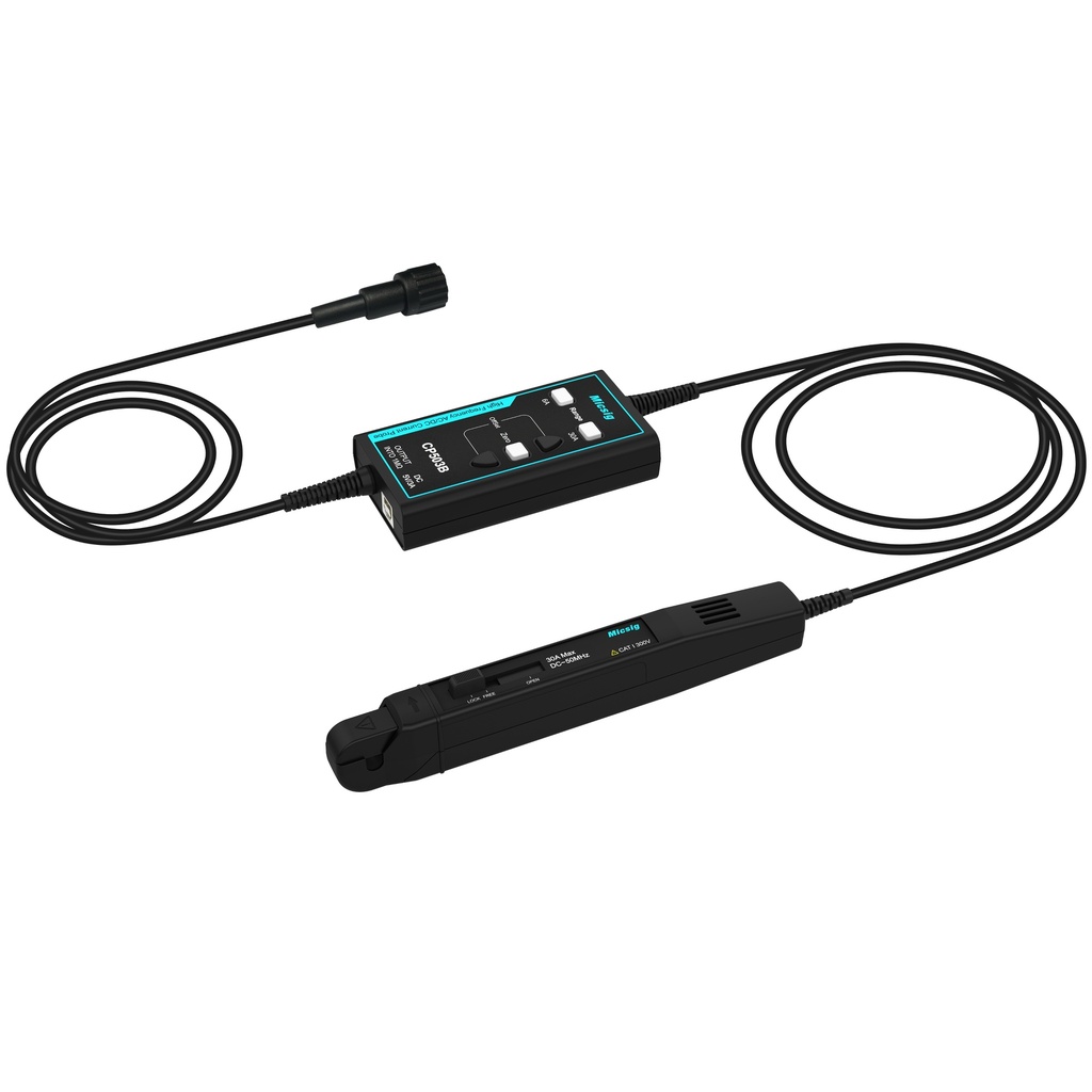
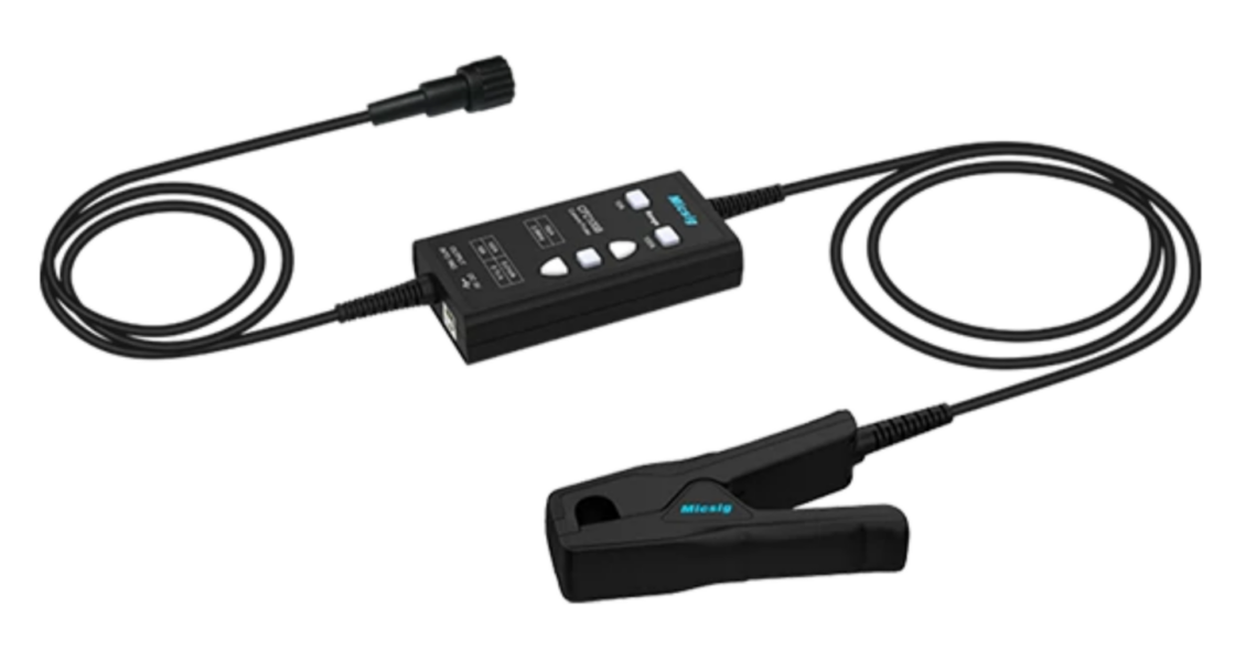
Current Probe CP503B
Current probe for oscilloscope-based current measurement and waveform analysis in electronics development and test environments.
View product
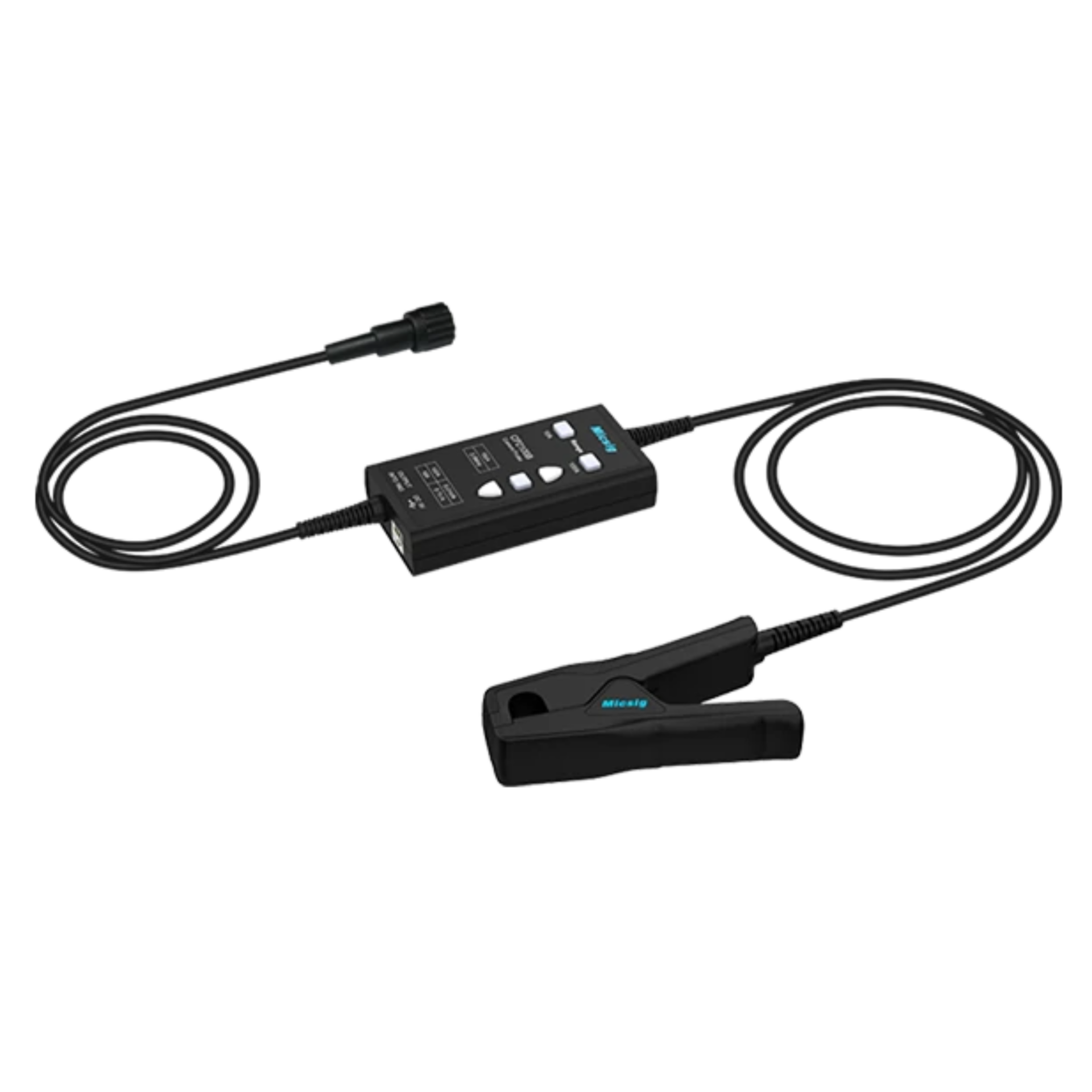
Current Probe CP2100B
Current probe for analyzing dynamic current signals in power electronics, switching applications, and laboratory measurement setups.
View product1. Oscilloscope Fundamentals for Current Measurement
An oscilloscope is primarily used to visualize electrical signals by plotting voltage as a function of time. This capability allows engineers to observe transient behavior, switching events, and waveform distortion that are difficult to detect using conventional measurement tools.
1.1 Role of the Oscilloscope in Power Analysis
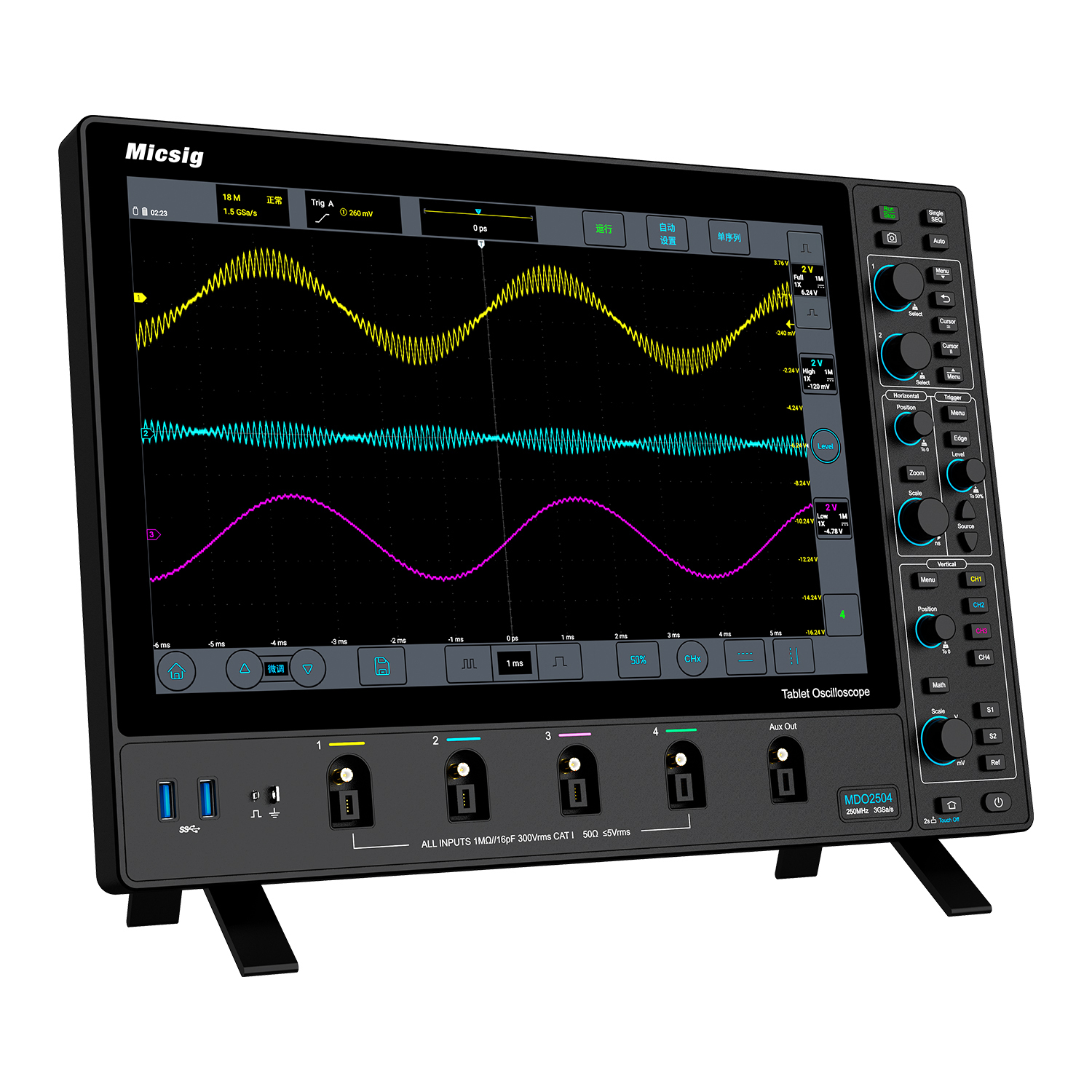
Power calculations require simultaneous measurement of voltage and current:
P = V × I
While voltage can be measured directly with a voltage probe, current must first be converted into a measurable signal. Current probes perform this conversion by acting as transducers that translate current flow into a proportional voltage output.
When voltage and current signals are measured simultaneously, modern oscilloscopes can calculate instantaneous power and derive additional metrics relevant to efficiency analysis.
1.2 Non-Intrusive Current Measurement with Clamp Probes
Traditional current measurements often require inserting a shunt resistor into the circuit. In contrast, clamp-style current probes measure the magnetic field surrounding a conductor.
This approach offers several practical advantages:
- No need to interrupt the circuit
- Reduced risk of altering circuit behavior
- Convenient measurement of dynamic current waveforms
These characteristics make clamp probes widely used in development, validation, and troubleshooting environments.
2. Selecting an Appropriate Current Probe
Current probes are designed for different measurement scenarios. Selecting a suitable model requires evaluating several key parameters related to the electrical characteristics of the application.
2.1 Core Specifications
Bandwidth and Rise Time
Bandwidth determines the highest frequency component that the probe can measure accurately. Applications involving switching converters or fast semiconductor devices typically require higher bandwidth.
If probe bandwidth is insufficient, the measured waveform may exhibit slower rise times and distorted switching transitions, which can affect loss calculations.
Measurement Range and Protection
The probe’s measurement range should accommodate both steady-state current and short-duration peaks such as inrush events.
Many probes include overload protection mechanisms designed to reduce the risk of damage during unexpected current surges.
Accuracy and Offset Calibration
Measurement accuracy becomes particularly important when analyzing small efficiency differences.
For AC/DC probes, degaussing and offset nulling procedures are commonly performed before measurements in order to minimize drift and measurement error.
2.2 Interface and Form Factor
Different probe interfaces are available depending on the intended measurement setup:
- BNC-connected probes: commonly used with laboratory oscilloscopes
- USB-powered probes: suitable for portable measurement systems or data logging
- Compact portable probes: useful for field service or on-site troubleshooting
2.3 Probes for Specialized Applications
Some measurement environments require probes designed for specific operating conditions.
Motor drives and inverters
Motor control systems often involve high peak currents and switching frequencies. Current probes used in these environments typically support larger measurement ranges.
Safety-critical or aerospace environments
In applications such as avionics testing, probes may be selected based on environmental robustness and compliance with relevant testing procedures.
3. Practical Power Efficiency Analysis
Once suitable measurement tools are selected, engineers can perform structured analysis to identify sources of energy loss.
3.1 Analysis of Switch-Mode Power Supplies (SMPS)
Switch-mode power supplies are often analyzed to evaluate conversion efficiency and switching behavior.
Typical measurement objectives include:
- Switching losses – observation of voltage/current overlap during transistor transitions
- Conduction losses – evaluation of RMS current through power components
- Inrush current – measurement of startup current peaks for soft-start circuit design
3.2 Inverter and Motor Drive Analysis
Power losses in motor systems occur both in the inverter electronics and in the motor itself.
Relevant measurements include:
- Harmonic distortion – waveform analysis of phase currents
- Dead-time effects – evaluation of switching timing between semiconductor devices
These measurements help engineers better understand current behavior in real operating conditions.
3.3 Profiling Battery-Powered Devices
For battery-operated systems, the average current consumption over time is a key parameter.
In such cases, probes with a wide dynamic range are useful because they allow measurement of both:
- Very low sleep currents
- Higher active operating currents
Logging current consumption across operational cycles provides a realistic estimate of average energy usage.
4. Translating Measurement Data into Design Improvements
Measurement results can provide valuable insights during circuit optimization and design refinement.
4.1 Typical Optimization Approaches
- Reducing switching losses by adjusting gate drive parameters or switching devices
- Reducing conduction losses by selecting components with lower resistance or improving PCB layout
- Optimizing magnetic components by adjusting inductance values or core materials
- Refining control algorithms to improve switching behavior in motor drives
4.2 Measurement Best Practices
- Minimize loop area when positioning the probe around the conductor
- Perform degaussing and offset calibration before precision measurements
- Synchronize voltage and current channels to reduce timing errors in power calculations
Conclusion
Accurate current measurement plays an important role in power efficiency analysis. When combined with an oscilloscope, current probes enable engineers to observe dynamic current behavior and evaluate power consumption in detail.
By applying appropriate measurement techniques and interpreting the resulting data carefully, engineers can gain useful insights into circuit operation and identify potential areas for efficiency improvement.


